18 SUPERBRUSH OWNER’S MANUAL
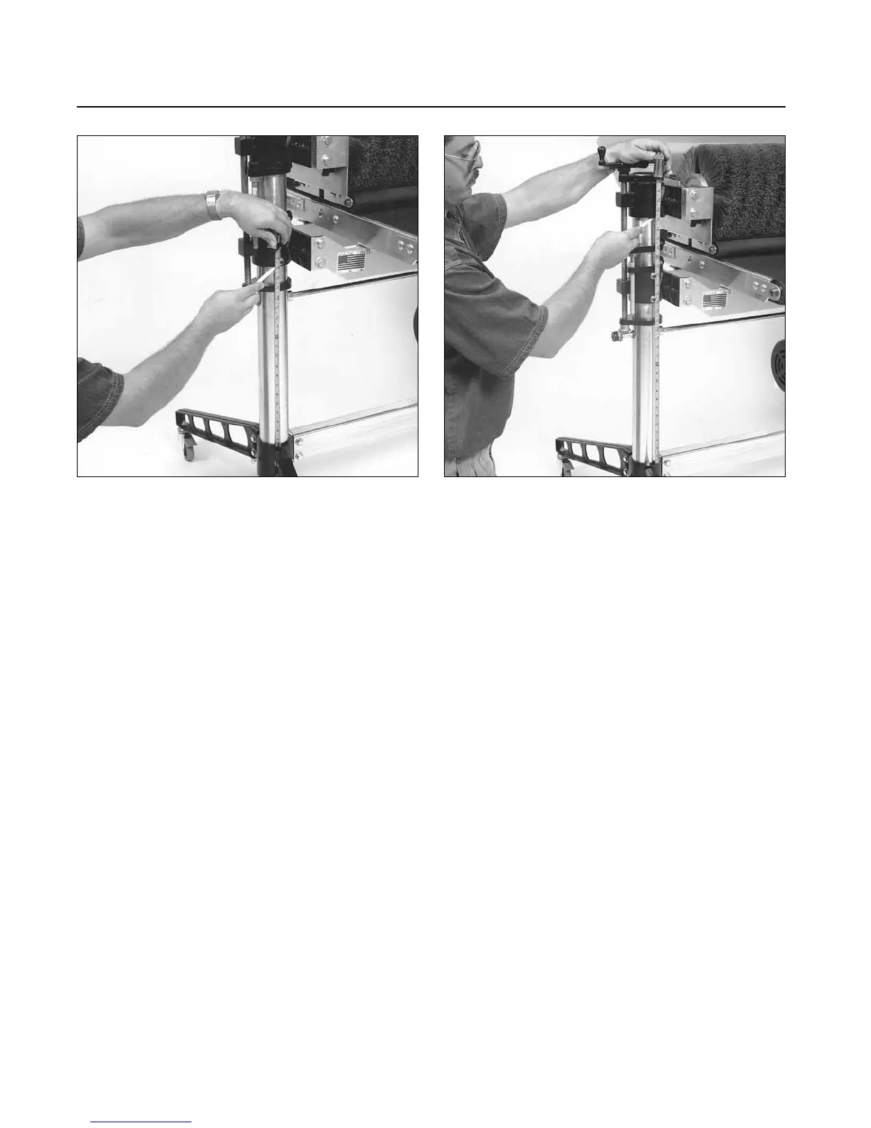
LEVELING TABLE
To measure levelness of table, measure the distance
between the top of the base casting (Fig. 17) and
the bottom of the table support castings. This
measurement should be the same for both sides. If
it is not the same, adjust as follows:
Remove the plastic cap from the miter gear (Fig.
14) on the outboard side of the machine. Loosen
the set screw of the miter gear and slide it back to
disengage it from the miter gear of the adjusting
screw. Turn the adjusting screw handle to raise or
lower the outboard side of the table so that the
measurement taken above equals the inboard side
of the table. After adjusting is complete, re-engage
miter gear making sure that miter gear set screw is
aligned with flat on cross bar shaft.
MITER GEAR ALIGNMENT
If height adjustment mechanism does not operate
easily, perform the following checks or adjustments:
1. Loosen set screws located on table support
castings. (Fig. 3).
2. Lubricate thoroughly! Apply penetrating lubricant
to table support castings where it contacts the
column tubes, and to all contact points of adjusting
screws and cross bar. Apply grease/oil to miter
gears.
3. Check miter gear alignment. Check and adjust
gears so that gear mesh is not too tight nor too
loose and that gear teeth align with opposing gear.
The miter gears can be adjusted on their shafts by
loosening the set screws on the gears. Note that set
screws MUST align with flat of shaft. To raise or
lower the vertical miter gears, the adjusting screw
support, located immediately above the gears,
must also be raised or lowered to ride on top of the
gear to maintain adjusting screw position.
If vertical miter gear is raised to its highest
position, then the adjusting screw (Fig. 5) must be
raised, if necessary, to obtain proper gear alignment.
Raise adjusting screws as follows:
Fig. 18. Comparing brush support casting heights.Fig. 17. Adjusting table support castings.