6 SUPERBRUSH OWNER’S MANUAL
Your SUPERBRUSH sander was adjusted and aligned
at the factory, and it has been carefully packed for
shipment. However, because of possible stress during
transit, the unit should be thoroughly checked
before being put to use. This section covers the
pre-operational checks you should make after
unpacking and final assembly. Unnecessary problems
can be avoided if these essential checks are performed
before operating. Likewise, performing the recom-
mended monthly maintenance procedures (page
11) will help assure trouble-free service.
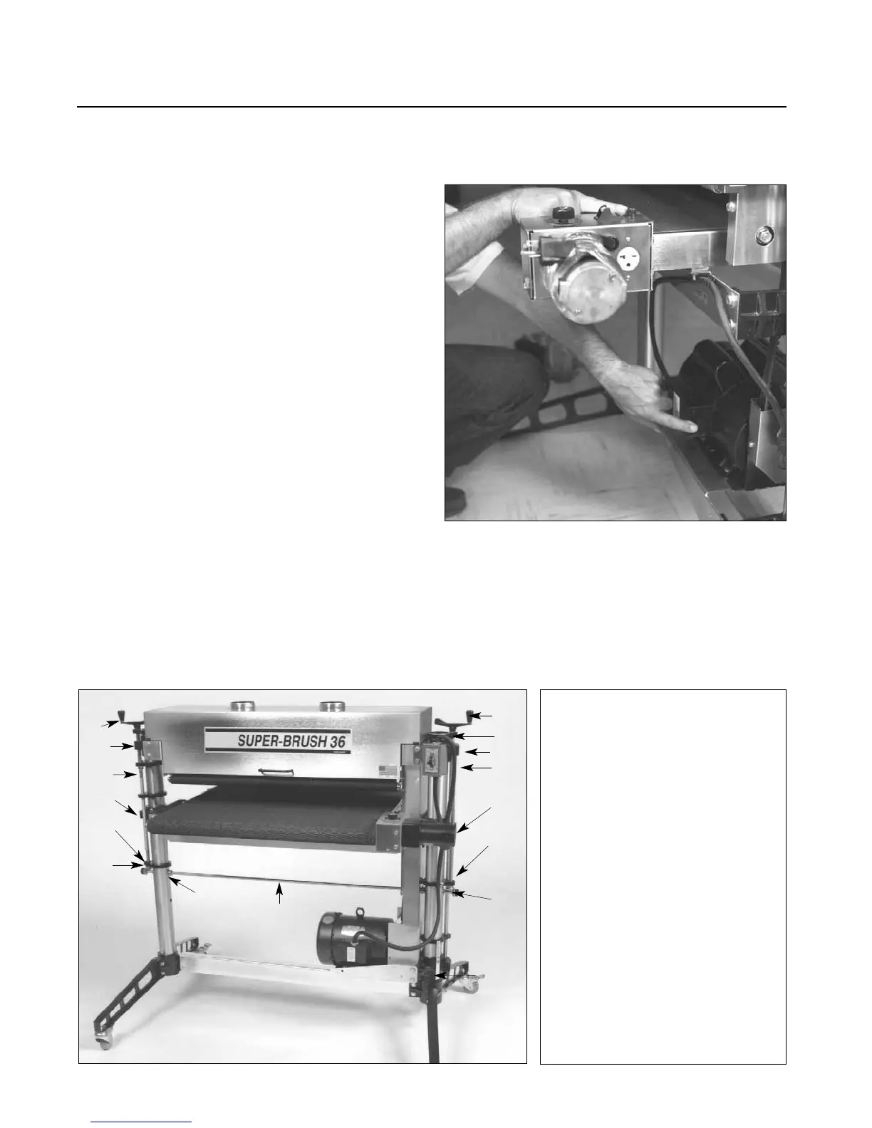
MAKING ELECTRICAL CONNECTIONS
Power for the brush of your SUPERBRUSH is supplied
by either a 5HP, single-phase, a 5HP, three phase,
208-230V motor; or a 5HP, three phase, 460V
motor.
- Single phase motor: Protected by a thermal
overload switch. On single phase machines, a
NEMA 14-30 plug is provided. A 30 amp breaker
is required.
- Three phase motor: No plug is provided. It can
be hard wired to a main power source or a plug
can be installed to be used with a receptacle.
- Three phase, 208V motors require a 20 amp
breaker.
SETTING UP YOUR SUPERBRUSH
Fig. 4. Thermal-overload switch on single phase
motor (bottom) and conveyor belt motor fuse (top).
Fig. 5. SUPERBRUSH Components.
1. Brush Speed Handle.
2. Adjusting Screw Support.
3. Brush Support Casting.
4. Height Adjusting Screw.
5. Table Support Casting.
6. Miter Gear.
7. Motor Support Casting.
8. Transfer Rod.
9. Shaft Collars.
10. Height Adjustment Handle.
1
2
3
4
5
2
10
3
4
5
2
6
9
6
7
8
- Three Phase, 460V motors require a 15 amp
breaker and 5 wire connections.