SETTING UP YOUR SUPERBRUSH 7
CONNECTING DUST COLLECTORS
Dust collection is necessary for all SUPERBRUSH
models. The SUPERBRUSH 24 is equipped with one
4˝ diameter dust exhaust port at the top of the
brush cover. The S
UPERBRUSH 36 has two 4˝ dust
exhaust ports.
To attach the S
UPERBRUSH to your collection
system, install 4˝ hose from your collector. (See
Tips For Maximum Performance, page 12 of this
manual.) The minimum recommended dust collector
capacities at the dust port(s) are: S
UPERBRUSH 24:
600
CFM; SUPERBRUSH 36: 1,200 CFM. For best
results, follow the recommendations of the manufac-
turer of your dust collection equipment. NOTE:
Some applications will require more dust collection
than the recommended minimum CFM.
CHECKING MACHINE FOR LEVEL
Proper leveling of the machine is essential to
achieve continued maximum performance from
the S
UPERBRUSH. Before making fine adjustments,
place the unit where it will be used in the shop.
Then adjust the four leveling feet using a carpenter’s
level both across the machine and in line with the
machine, placing the level on the conveyor bed. If
you have equipped your S
UPERBRUSH with the
optional caster set, do the same after positioning
the machine where it will be operated most often.
Mark the position of the legs on the floor with
tape so it can be returned to the same position.
HEIGHT ADJUSTMENT
The table height is controlled by the height adjust-
ment handle (10)(Fig.5). Turning the handle raises
or lowers both sides of the table simultaneously by
transferring the handle rotation through the miter
gear and transfer rod assembly. One revolution of
the handle raises or lowers the table 3/32 of an
inch.
Before operating height adjustment, be sure both
set screws located in both table support castings
(Fig. 3) are loose to allow table support to slide on
both column tubes. (These set screws are tightened
for shipping.)
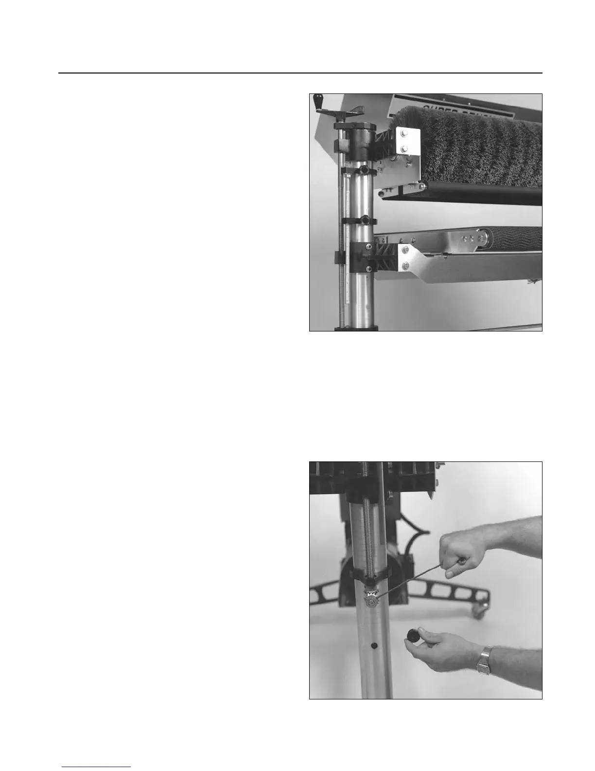
BRUSH ALIGNMENT
The brush must be parallel to the conveyor bed
surface. Brush alignment can be visually checked by
raising the tension rollers (Fig. 6) to their highest
position (See Tension Roller Adjustment page 9)
and raising the table so that the brush just contacts
the conveyor surface. Brush contact should be
Fig. 6. Checking brush alignment and table height
adjustment (outboard side).
Fig. 7. Adjusting brush alignment.