SERVICING YOUR SUPERBRUSH 19
Inboard follow screw (right): Loosen and raise
adjusting screw support (Fig. 5).Loosen both set
screws located on front of brush support casting
and raise inboard side of brush, screw and table to
desired height. Retighten set screws of brush support
casting (Fig. 3) and re-position and tighten
adjusting screw support at top of miter gear. The
brush and conveyor table must be re-aligned after
this adjustment. See Leveling Table and Brush
Alignment (page 7).
Outboard Adjusting Screw (left): Loosen and raise
adjusting screw support (Fig. 5) above miter gear.
Tighten set screw at front of outboard table support
casting. Loosen set screw and disengage opposing
horizontal miter gear. Turn adjusting screw handle
to raise screw to desired height. Re-position
adjusting screw support to bottom of handle.
Re-position adjusting screw support (Fig. 17) to
top of miter gear. Loosen set screws of table support
casting (Fig. 3). Re-engage opposing horizontal
miter gear. NOTE: Shaft collars (Fig. 10) located
on the transfer rod should be adjusted to control
lateral movement of the transfer rod to maintain
accurate miter alignment and mesh.
4. Check and adjust for misalignment of adjusting
screw supports (Fig. 5) and brush support castings
which could cause binding on the adjusting screw.
These castings can be slightly rotated by loosening
the set screws which secure it to the inside of the
column tubes. NOTE: The adjusting screw support
(Fig. 5) located immediately below the height
adjusting handle and the outboard brush support
casting, must be set at the proper height along the
column tubes to position the adjusting screws so
that there is proper miter gear alignment. Before
adjusting these parts, tighten one set screw of table
support castings to maintain adjusting screw
position during adjustment.
BRUSH SPEED ADJUSTMENT
If the brush speed adjustment does not operate
easily, perform the following check or adjustments:
1. Loosen set screws located on front of motor
support casting (Fig. 3).
2. Lubricate thoroughly!! Apply penetrating lubricant
to motor support casting where it contacts the
column tubes and to all contact points between
adjusting screw and adjusting screw supports (Fig.
5).
3. Improper alignment of adjusting screw supports
may cause binding on the adjusting screw. Loosen
both set screws on each adjusting screw support to
rotate or adjust screw supports. Note that adjusting
screw supports control both lateral and vertical
movement of the adjusting screw mechanism and
must be adjusted accordingly.
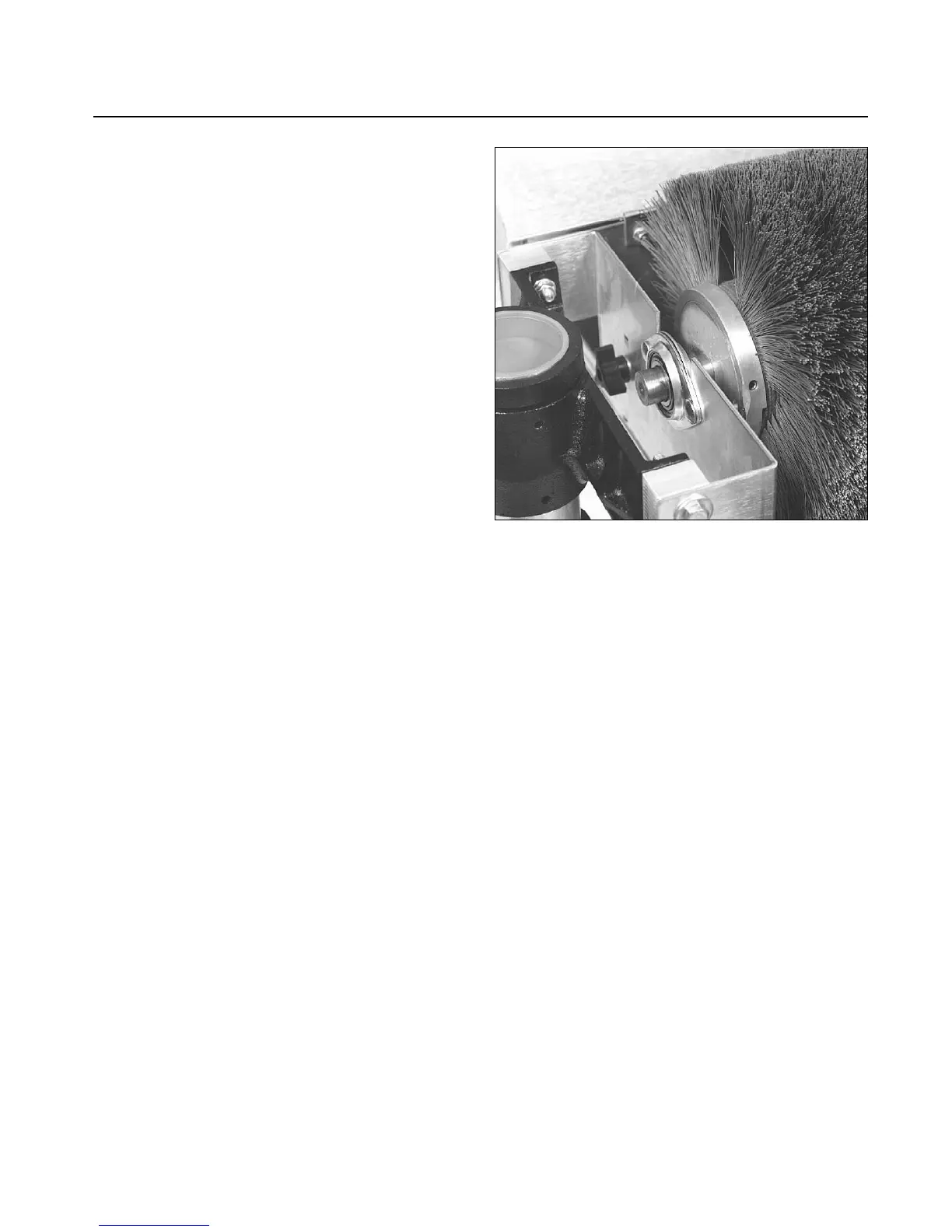
Fig. 19. Removing brush head.