24 SUPERBRUSH OWNER’S MANUAL
and the bearing flange for one bearing at a time.
Spin the brush within the collar, then tighten the
bolts in the bearing flange and then the set screws.
9. Test-run the S
UPERBRUSH before brushing stock
to check that all is operating properly and is
aligned before brushing good stock. Also, stop the
S
UPERBRUSH after a couple hours of use and check
the bolts and set screws to make sure they are seated
properly.
RR
EEPPLLAACCIINNGG
EE
LLEECCTTRRIICCAALL
CC
OOMMPPOONNEENNTTSS
To replace either the variable-speed controller, or
the conveyor motor, use the following disassembly
procedure (Fig. 26 and pages 25 and 26):
Disconnect the power supply to the machine.
Next, remove the bottom plate from the control
box. Loosen the set screw in the shaft coupler, and
then remove the four 5/16˝ bolts that hold the
power feed motor assembly in place. Next, remove
the assembly from the machine and turn it upside
down to disconnect the leads from the components
to be removed.
To replace the controller, remove the variable
speed control knob. Remove the nut that holds
the controller in place and pull the controller out
of the housing. Install the new controller, referring
to the correct electrical diagram and reverse the
disassembly procedure.
To replace on/off switch, make sure power is
disconnected to sander. Remove the two screws
holding the front cover of the switch in place.
Disconnect and mark wire leads connected to
switch mechanism. Remove switch from box and
install new switch. Connect wires to new switch
following the wiring diagram and marked wires.
IMPORTANT: Make sure bare wire does not
touch any other wire or the switch box when
connected. Install switch assembly and cover.
To replace the conveyor gear motor, disconnect
the two wire leads from the controller. Also
disconnect the plastic grommet protecting the
wires passing through the housing. Remove the
four cap head set screws that hold the motor to the
housing bracket. Remove the old motor and
install new motor. Install the wiring leads according
to the electrical diagram pertaining to the correct
model (See following diagrams).
To replace conveyor fuse (Fig. 4), push and
turn fuse cap 1/8 turn counter clockwise. Pull cap
with fuse from base. Pull fuse from cap and
replace with 3/4 amp fuse (pages 25 and 26).
Place fuse and cap into base, push and turn 1/8
turn clockwise to secure.
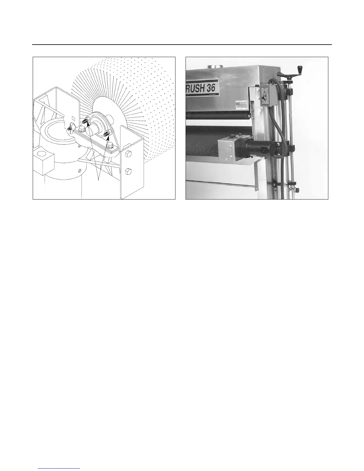
Fig. 25. Supporting brushes to remove bearings. Fig. 26. Conveyor motor control box and brush
on/off switch.
BEARING
BOLTS