ABOUT THE SUPERBRUSH SYSTEM 5
UNPACKING YOUR SUPERBRUSH
Your SUPERBRUSH sander has been shipped completely
assembled from the factory in a shroud on a pallet
and shrink-wrapped in plastic. If any damage has
occurred as a result of shipment, notify the trans-
portation company as soon as possible and ask
them to make an immediate inspection. Ask for a
damage or loss report. Also notify your dealer of
any loss or damage during shipment. See enclosed
Warranty Statement.
Important: To avoid problems and potential
damage to the machine, please read through the
unpacking instructions below before proceeding to
set up the machine in your shop.
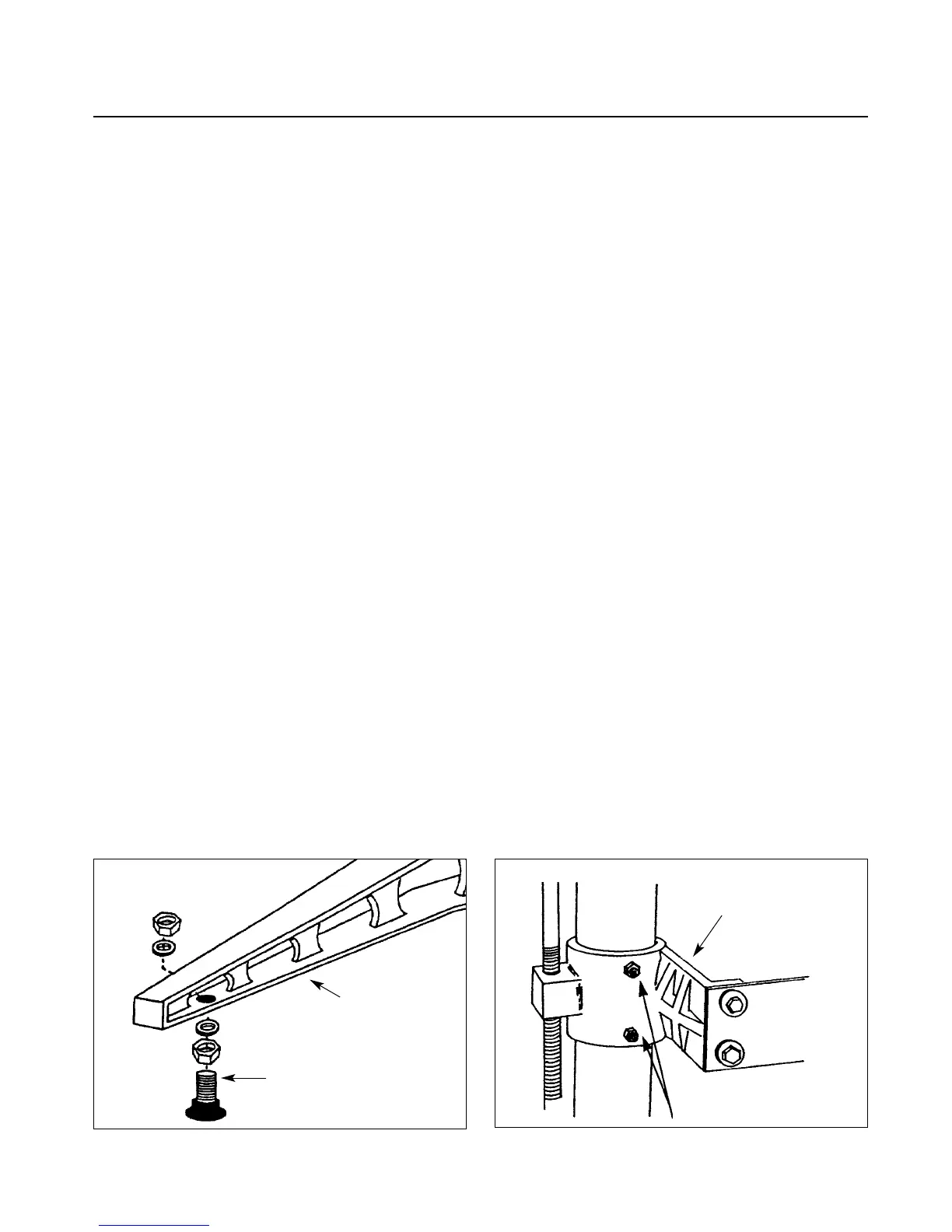
1. Unbolt the machine legs from the shipping
pallet. Install the rubber-based leveling feet or
optional caster set on legs (Fig. 2). The feet and
mounting hardware are in the STOP bag packed
with your machine.
2. Loosen the hex nuts and set screws on the
table support castings (Fig. 3) and on the motor
support casting (7)(Fig. 5). The set screws on the
table support castings have been tightened at the
factory to eliminate free-play between the castings
and the column tube during shipment. There are
two table support castings on the S
UPERBRUSH,
one each for the right and left column tubes, and
one motor support casting, all with set screws.
Important: These set screws are tightened for
shipping and must be loosened and readjusted
before operating either the height adjustment
mechanism or the brush speed control handle.
To properly adjust for operation, loosen each set
screw by first loosening its hex nut with a wrench
and then the set screw with an Allen wrench. Then
retighten each set screw with your fingers so it only
lightly touches the column tube. Hold each set
screw in position with an Allen wrench and
retighten the hex nut. Failure to follow these
procedures may result in misalignment of the
brush and/or the conveyor table.
Caution: Do not loosen the set screws on the
upper brush support castings.
Note: Some machines have a block of wood
under the main motor. If so, remove at this time.
3. Install the conveyor gear motor. Rotate the
drive roller on the conveyor system so the flat part
of the shaft is down. If necessary, connect the
conveyor motor into an appropriate AC outlet (see
page 6, “Making Electrical Connections”), to
rotate the motor output shaft coupling so the set
screws face downward. Disconnect electrical supply.
Slide the conveyor motor assembly onto the drive
roller shaft, aligning the shaft coupling and four
mounting holes. Start the four 5/16” hex head
bolts on the conveyor motor mounting bracket,
but do not tighten yet.
Next, tighten the set screws in the coupling on
the drive roller shaft, making sure they are on the
flat of the shaft. Rock the drive roller while tight-
ening the set screws to make sure they are centered
properly on the flat. Install the bottom cover on
the control box with two screws. Then connect
power to machine and turn conveyor on full speed.
While it is running, tighten the four 5/16" bolts to
secure the conveyor motor assembly in place.
Fig. 2. Leveling foot and mounting hardware. Fig. 3. Table support casting and set screws.
LEVELING FOOT
STAND LEG
TABLE SUPPORT
CASTING
HEX NUT & SET SCREW