SERVICING YOUR SUPERBRUSH 23
Replacing Right (Inboard) Bearing:
Disconnect power source to brush.
1. Lower motor to its lowest position using the
RPM adjustment handle. Then raise motor to its
highest position using the RPM adjustment handle.
This loosens the V-belt tension so the V-belt can
be lifted off the driven pulley.
2. Raise conveyor table so brush rests on conveyor.
3. Remove left (outboard) bearing by removing the
two carriage bolts from bearing.
4. Remove the right (inboard) bearing by removing
the two carriage bolts from bearing.
5. Remove V-belt from driven pulley.
6. Lift brush head out from machine.
7. Loosen set screws in bearing collar and driven
pulley and remove from brush shaft.
8. Install new bearing and driven pulley. Do not
tighten set screws at this time.
9. Install brush in machine and center before
tightening bolts. Tighten bearing bolts and then
set screws in bearings.
10. Install V-belt on driven pulley and adjust pulley
for proper V-belt alignment before tightening
pulley set screw.
11. Check the alignment of the brush to the
conveyor system.
REPLACING BRUSH HEAD
1. Lower motor to its lowest position using the
RPM adjustment handle. Then raise motor to its
highest position using the RPM adjustment handle.
This loosens the V-belt tension so the V-belt can
be lifted off the driven pulley.
2. Remove the bearing bolts (Fig. 19, 19A and 25)
and lift brush out of machine. Note: Some models
have two mounting bolts attaching the bearing
housing down into the brush support bracket.
These two bolts can be used to remove the brush
head instead of the bolts through the bearing
flange.
3. Loosen set screws in bearing collars and driven
pulley and remove from brush shaft.
4. Install new bearings and driven pulley. Do not
tighten set screws at this time.
5. Install brush in machine and center before
tightening bearing bolts. Tighten bearing bolts
and then set screws in bearings.
6. Install V-belt on driven pulley and adjust pulley
for proper V-belt alignment before tightening
pulley set screw.
7. Check the alignment of the brush to the conveyor
system. (For instructions on this procedure, see
page 7 of this manual).
8. Lower the conveyor and spin the brush by hand
to make sure the brush shaft is not binding in the
bearing. If the bearings bind, loosen the set screws
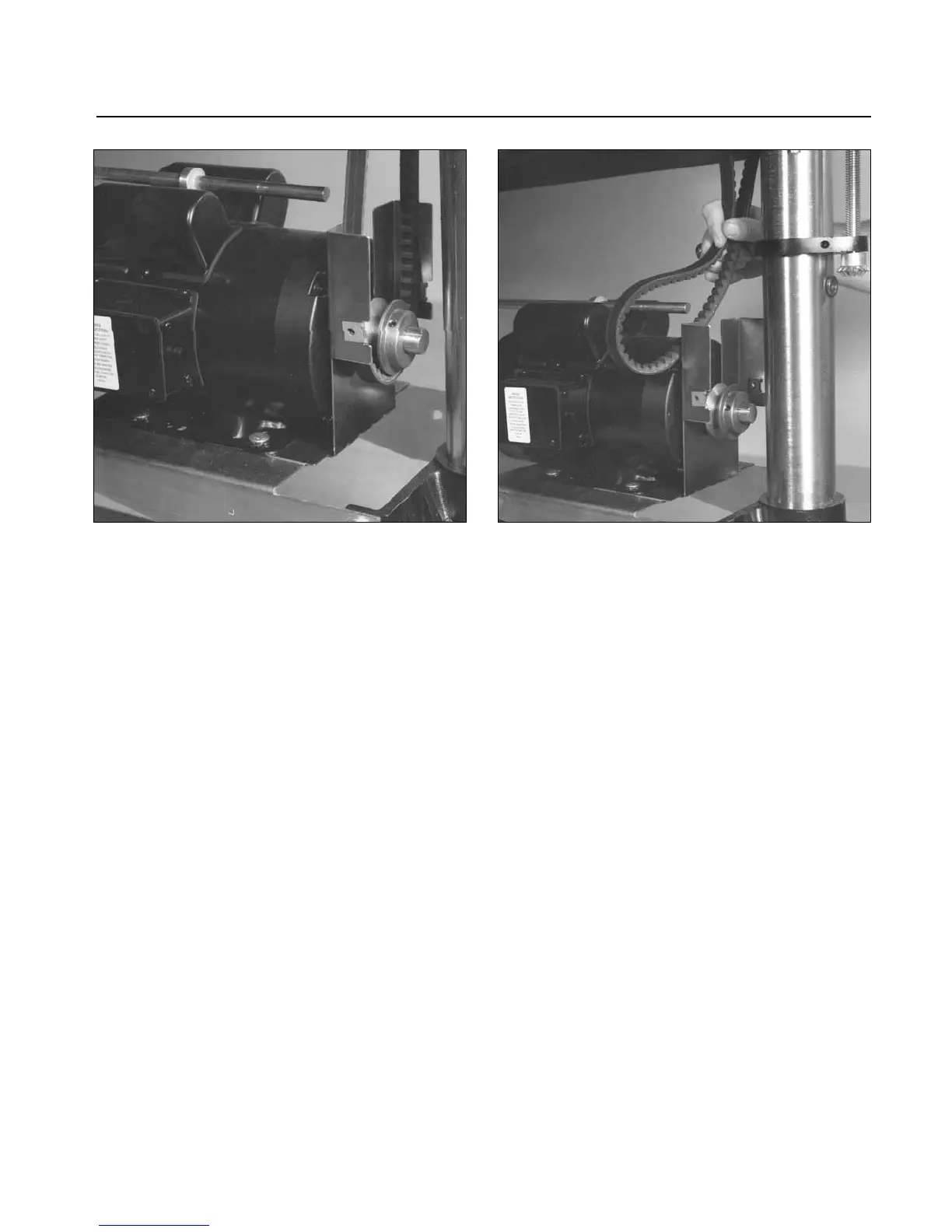
Fig. 23. Removing lower guard and transfer rod. Fig. 24. Removing main motor V-belt drive.