Chapter 1: Introduction
1-5
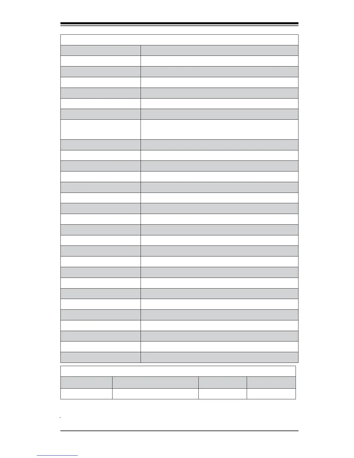
C7Q67 Headers/Connectors
Connector Description
Audio_FP Front Panel Audio Header
HD Audio High-Denition Audio Connectors (on the I/O back panel)
B1 Onboard Battery
COM1/COM2/COM3/COM4 COM1 Port (Back Panel) COM 2/3/4 Serial Port Headers
BIOS AMI SPI BIOS
Fan1~Fan4 System/CPU Fan Headers (Fan1: CPU Fan)
JCPUVRD SMB CPU Overclocking SMB(System_Management_Bus) Header
(Note)
JD1 Speaker/buzzer (Pins 1-2: Buzzer, Pins 1~4: External Speaker)
JF1 Front Panel Control Header
JL1 Chassis Intrusion Header
JLED Power LED Indicator Header
JPW1 24-pin ATX Main Power Connector (Required)
JPW2 +12V 4-pin CPU power Connector (Required)
KB/Mouse Keyboard/Mouse Connectors
LAN1/LAN2 Gigabit (RJ45) Ports (LAN1/2)
JSPDIF_In/JSPDIF_OUT SPDIF_(Sony/Philips Digital Interface)_In/ SPDIF_Out Headers
JWF1 SATA DOM (Device_On_Module) Power Connector
JWOL Wake_On_LAN Header
JWOR Wake_On-Ring Header
Slot 7 PCI-Express 2.0 x16 Slot
Slot 6 PCI-Express 2.0 x1 Slot
Slot 4 PCI 33MHz Slot (5V)
Slot 5 PCI-Express 2.0 x4 Slot
(I-)SATA (3.0) 0/1, (2.0) 2~5 (Intel) Serial ATA 3.0 Ports 0/1. Serial ATA 2.0 2~5
SP1 Internal Buzzer
USB (2.0) 10/13, 8/9 Backpanel USB 2.0 Ports 10/13, 8/9
USB (3.0) 0/1 Backpanel USB 3.0 Ports 0/1
USB2/3, USB4/5, 11/12 Front Accessible USB Connections 2/3, 4/5, 11/12
C7Q67 LED Indicators
LED Description Color/State Status
LED1 Onboard Standby PWR LED Green: Solid on Power On