EasyManuals Logo

Supero C7Q67 User Manual

Supero C7Q67
93 pages
To Next Page IconTo Next Page
To Previous Page IconTo Previous Page
Page #43 background imageLoading...
Page #43 background image
Chapter 2: Installation
2-19
Power Button
OH/Fan Fail LED
1
NIC1 LED
Reset Button
2
HDD LED
Power LED
Reset
PWR
LED_Anode+
LED_Anode+
LED_Anode+
LED_Anode+
Ground
Ground
X
X
NIC2 LED
LED_Anode+
FrontControlPanelPinDenitions
Power LED
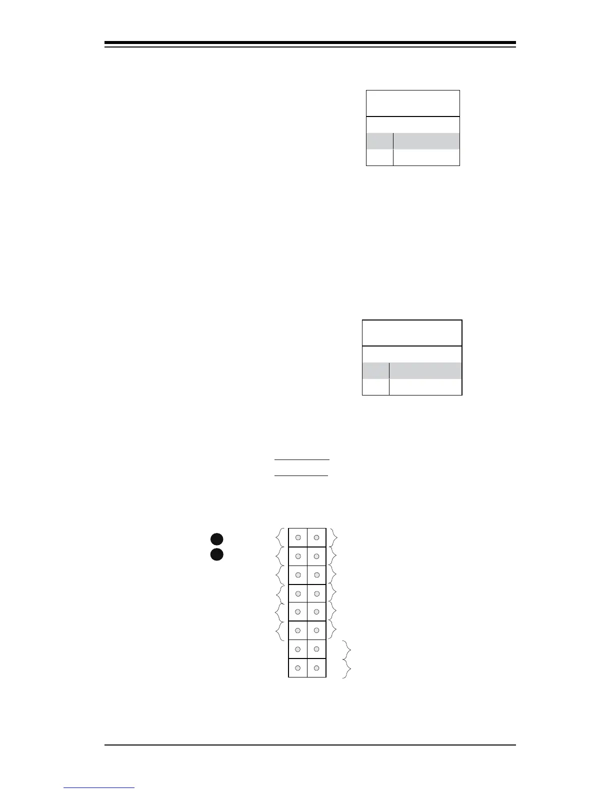
The Power LED connection is located
on pins 15 and 16 of JF1. Refer to the
table on the right for pin denitions.
Power LED
PinDenitions(JF1)
Pin# Denition
15 +5V
16 Ground
A. PWR LED
B. HDD LED
A
B
HDD LED
The HDD LED connection is located
on pins 13 and 14 of JF1. Attach a
cable here to indicate the status of
HDD-related activities, including IDE,
SATA activities. See the table on the
right for pin denitions.
HDD LED
PinDenitions(JF1)
Pin# Denition
13 +5V
14 HD Active

Table of Contents

Questions and Answers:

Question and Answer IconNeed help?

Do you have a question about the Supero C7Q67 and is the answer not in the manual?

Supero C7Q67 Specifications

General IconGeneral
BrandSupero
ModelC7Q67
CategoryMotherboard
LanguageEnglish

Related product manuals