2-22
C7Q67 User's Manual
2-6 Connecting Cables
This section provides brief descriptions and pin-out denitions for onboard headers
and connectors. Be sure to use the correct cable for each header or connector. For
information on Backpanel USB and Front Panel USB ports, refer to Page 2-17. For
Front Panel Audio, please refer to Page 2-19.
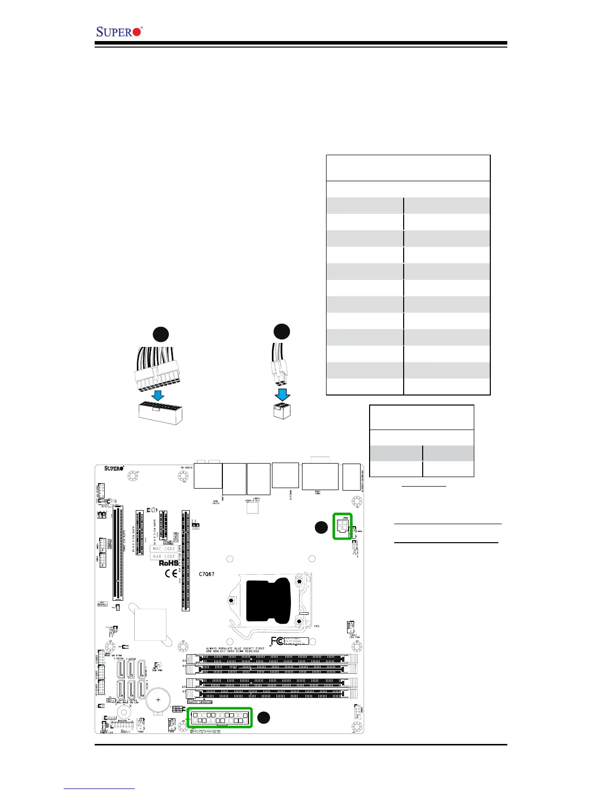
A. 24-Pin ATX Main PWR
B. 4-Pin Processor PWR
ATX Power 24-pin Connector
PinDenitions(JPW1)
Pin# Denition Pin # Denition
13 +3.3V 1 +3.3V
14 -12V 2 +3.3V
15 COM 3 COM
16 PS_ON 4 +5V
17 COM 5 COM
18 COM 6 +5V
19 COM 7 COM
20 Res (NC) 8 PWR_OK
21 +5V 9 5VSB
22 +5V 10 +12V
23 +5V 11 +12V
24 COM 12 +3.3V
(Required)
12V 8-pin Power Connec-
torPinDenitions
Pins Denition
1 through 4 Ground
5 through 8 +12V
ATX Main PWR & CPU PWR
Connectors (JPW1 & JPW2)
The 24-pin main power connector
(JPW1) is used to provide power to
the motherboard. The 4-pin CPU PWR
connector (JPW2) is also required for
the processor. These power connectors
meet the SSI EPS 12V specication. See
the table on the right for pin denitions.
4-Pin Processor PWR
A
B
24-Pin Main PWR
A
B