Chapter 2: Installation
2-15
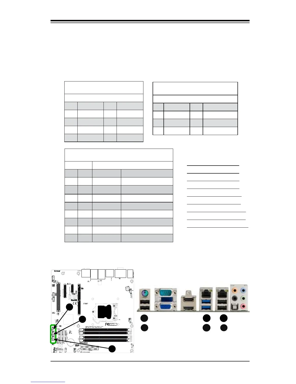
A. Backpanel USB 2.0 #9
B. Backpanel USB 2.0 #8
C. Backpanel USB 3.0 #0
D. Backpanel USB 3.0 #1
E. Backpanel USB 2.0 #13
F. Backpanel USB 2.0 #10
G. Front Panel USB 2.0 #4/5
H. Front Panel USB 2.0 #2/3
I. Front Panel USB 2.0 #11/12
Universal Serial Bus (USB)
Four Universal Serial Bus 2.0 ports (8/9, 13/10) are located on the I/O back panel,
in addition to two USB 3.0 Ports (0/1) that are located below LAN1. USB headers
2/3, 4/5 & 11/12 are used to provide front chassis access using USB cables (not
included). See the tables below for pin denitions.
Back Panel USB (2.0) #8/9, 13/10
PinDenitions
Pin# Denition Pin# Denition
1 +5V 5 +5V
2 USB_PN1 6 USB_PN0
3 USB_PP1 7 USB_PP0
4 Ground 8 Ground
Front Panel USB (2.0) #2/3, 4/5, 11/12
PinDenitions
Pin # Denition Pin # Denition
1 +5V 2 +5V
3 USB_PN2 4 USB_PN3
5 USB_PP2 6 USB_PP3
7 Ground 8 Ground
9 Key 10 Ground
A
Back Panel USB (3.0) #0/1
PinDenitions
Pin# Pin# Signal Name Description
1 10 VBUS Power
2 11 D- USB 2.0 Differential Pair
3 12 D+
4 13 Ground Ground of PWR Return
5 14 StdA_SSRX- SuperSpeed Receiver
6 15 StdA_SSRX+ Differential Pair
7 16 GND_DRAIN Ground for Signal Return
8 17 StdA_SSTX- SuperSpeed Transmitter
9 18 StdA_SSTX+ Differential Pair
C
E
B