2-6
SUPER P4DC6/P4DC6+/P4DC6+II/P4DCE/P4DCE+/P4DCE+II User's Manual
2-5 Port/Control Panel Connector Locations
The I/O ports are color coded in conformance with the PC99 specification to
make setting up your system easier. See Figure 2-4 (below) for the colors and
locations of the various I/O ports.
Figure 2-4. I/O Port Locations and Definitions
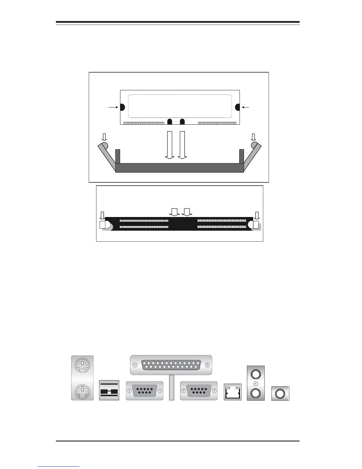
Figure 2-3. RIMM Installation
Note: Notches
should align
with their
receptive points
on the slot.
RIMM Slot
Side View of RIMM Installation into Slot
RIMM
Tab
Notch
Tab
Notch
Tab Tab
To Install: With the tabs pulled outward, insert the RIMM module
vertically and press straight down until it snaps into place. Pay
attention to the alignment of the two notches.
Top View of RIMM Slot
Tab Tab
To Remove: Use your thumbs to gently push out the tabs at
both ends of the module. This should release it from the slot.
Parallel Port
(Burgundy)
COM1 Port
(Turquoise)
Keyboard
(Purple)
Mouse
(Green)
USB
Ports-0/1
(Black)
COM2 Port
(Turquoise)
LAN
(Black)
Line Out
(Lime)
Line In
(Blue)
Mic
(Pink)