Chapter 2: Installation
2-13
CD Headers
There are two CD headers of differ-
ent sizes on the motherboard for
audio CD playback. You must con-
nect an audio cable from your CD
player to the header that fits your
cable's connector. Refer to Table
2-20 for pin definitions.
Overheat LED (JOH)
The JOH header is used to connect
an LED to provide warning of chas-
sis overheating. It is located near
the microphone connector. Refer
to Table 2-22 for pin definitions.
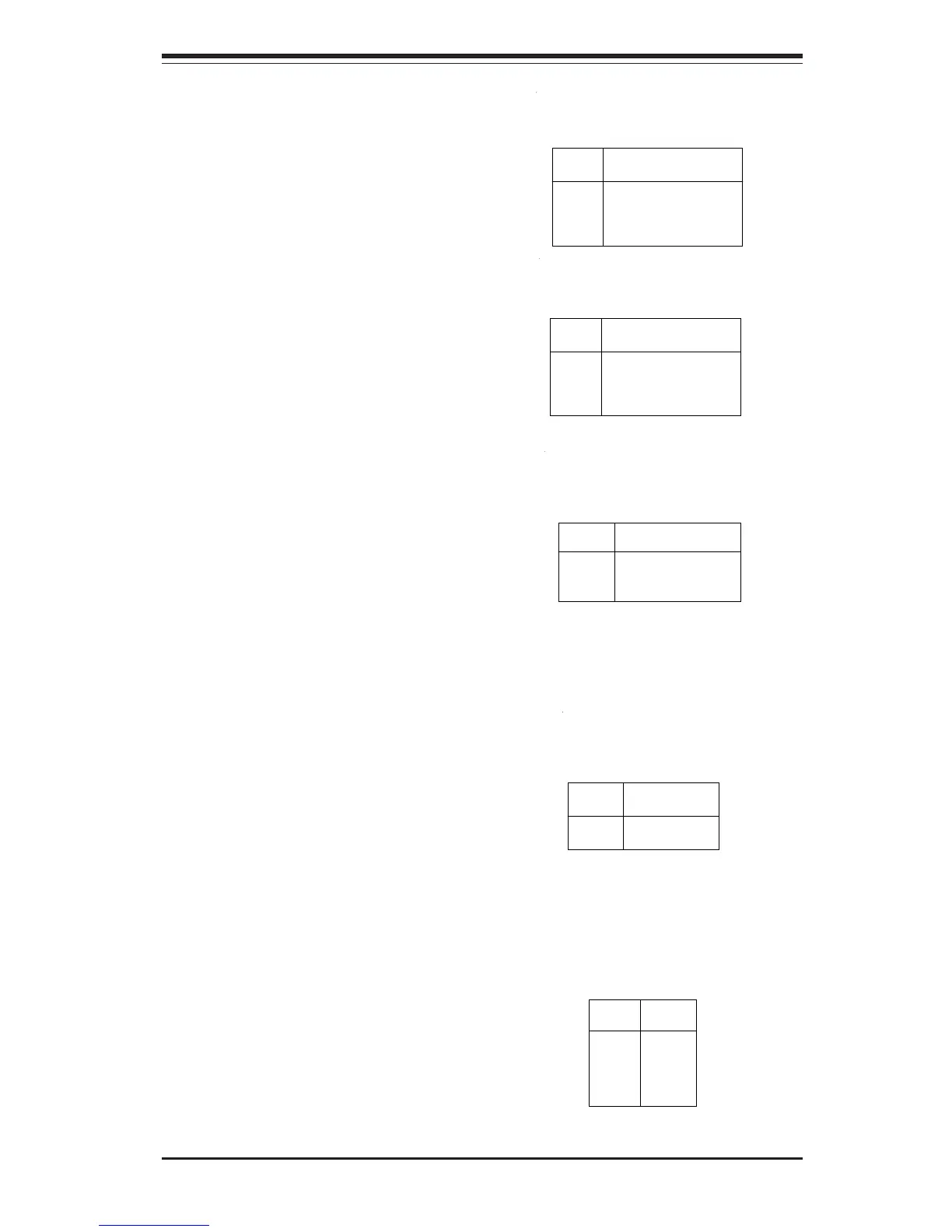
Pin
Number
1
2
Definition
12vDC
OH Active
Table 2-22
Overheat LED
Pin Definitions (JOH)
Fan Headers*
The CPU fans, chassis fans and
thermal control fan headers are
designated CPU FAN #1/#2, Chas-
sis Fan 1/2/3/4 and OH Fan respec-
tively. Refer to Table 2-21 for pin
definitions.
Table 2-21
Fan Header (CPU Fan 1-2,
Chassis Fan 1-4, OH Fan) Pin
Definitions
Pin
Number
1
2
3
Definition
Ground (black)
+12V (red)
Tachometer
*Caution: These fan headers are
for DC power only.
Table 2-20a
Audio CD Header Pin Definitions
(CD1)
Pin
Number
1
2
3
4
Definition
Left Stereo Signal
Ground
Ground
Right Stereo Signal
Table 2-20b
Audio CD Header Pin Definitions
(CD2)
Pin
Number
1
2
3
4
Definition
Right Stereo Signal
Ground
Ground
Left Stereo Signal
Infrared Connector
The infrared connector is located at
J32. See Table 2-23 for pin defini-
tions. See the Technical Support
section of our web site for informa-
tion on the infrared devices you can
connect to the system.
Pin
Number
1
2
3
4
5
Definition
+5v
Key
IRRX
Ground
IRTX
Table 2-23
Infrared Pin
Definitions (J32)