2-8
SUPER P4DC6/P4DC6+/P4DC6+II/P4DCE/P4DCE+/P4DCE+II User's Manual
Important !! The P4DC6/P4DC6+/
P4DC6+II/P4DCE/P4DCE+/
P4DCE+II must be connected
to supplemental 12v power
with the 4-pin J23 connector
and
the 8-pin J24 connector.
Failure to use a power supply
without such supplemental
12v power will result in CPU
instability after only a few min-
utes of operation.
Table 2-1b
ATX Power Supply 20-pin Connector
Pin Definitions
Pin Number Definition
11 +3.3v
12 -12v
13 GND
14 PS_ON
15 GND
16 GND
17 GND
18 -5v
19 +5v
20 +5v
Pin Number Definition
1 +3.3v
2 +3.3v
3 GND
4 +5v
5 GND
6 +5v
7 GND
8 PW-OK
9 5vSB
10 +12v
12345678901234567890123456789
1
234567890123456789012345678
234567890123456789012345678
234567890123456789012345678
234567890123456789012345678
234567890123456789012345678
9
12345678901234567890123456789
1234567890123456789012345
1
5
1234567890123456789012345
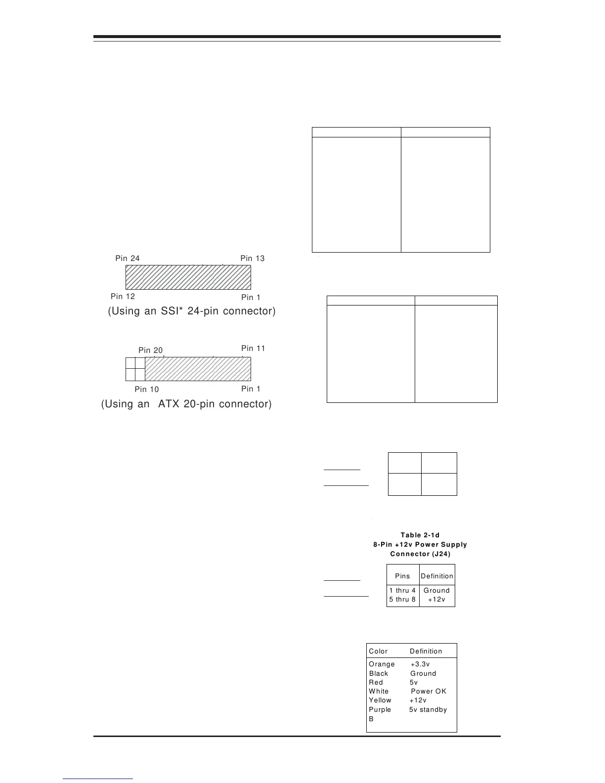
(Using an SSI* 24-pin connector)
(Using an ATX 20-pin connector)
Pin 1
Pin 1
Pin 12
Pin 24 Pin 13
Pin 10
Pin 11
Pin 20
Pins
1 thru 4
5 thru 8
Definition
Ground
+12v
Table 2-1d
8-Pin +12v Power Supply
Connector (J24)
Color Definition
Orange +3.3v
Black Ground
Red 5v
White Power OK
Yellow +12v
Purple 5v standby
Brown -5v
(For reference only)
Table 2-1e
P/S Wire Definitions
Pins
1 & 2
3 & 4
Definition
Ground
+12v
Table 2-1c
4-Pin +12v Power Supply
Connector (J23)
2-6 Connecting Cables (see previous page for locations)
Power Supply Connector
The primary power supply con-
nector on the P4DC6/P4DC6+/
P4DC6+II/P4DCE/P4DCE+/P4DCE+II
meets the SSI (Superset ATX)
24-pin specification and also
supports an ATX 20-pin connec-
tor.
Pin Number Definition
13 +3.3v
14 -12v
15 GND
16 PS_ON#
17 GND
18 GND
19 GND
20 Res(NC)
21 +5v
22 +5v
23 +5v
24 GND
Pin Number Definition
1 +3.3v
2 +3.3v
3 GND
4 +5v
5 GND
6 +5v
7 GND
8 PWR_OK
9 5vSB
10 +12v
11 +12v
12 +3.3v
Table 2-1a
ATX Power Supply 24-pin Connector
Pin Definitions
* SSI = Server System Infrastructure,
a specification for chassis power
supplies. Get more info at
http://www.ssiforum.org
Required
connection
Required
connection