2-10
SUPER P4DC6/P4DC6+/P4DC6+II/P4DCE/P4DCE+/P4DCE+II User's Manual
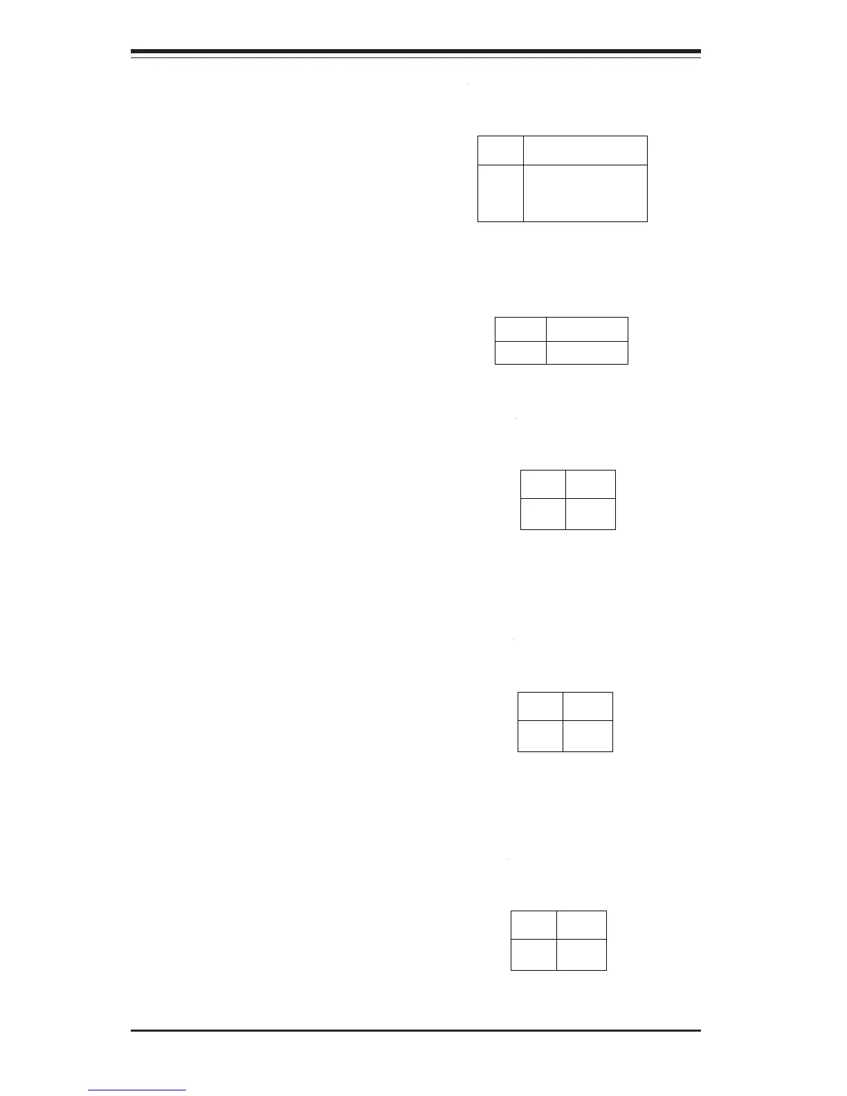
USB Keyboard
If you are using a USB keyboard,
connect it to pins 25, 27, 29, 31 and
33 of JF1. See Table 2-6 for pin
definitions.
Fan Fail LED
Connect the proper fan cable to
pins 4 and 6 of JF1 for LED indica-
tion of a fan failure. You will need a
fan fail cable (not included) to use
this connection. See Table 2-8 for
pin definitions.
Pin
Number
4
6
Definition
5v
Signal
Table 2-8
Fan Fail LED Pin
Definitions (JF1)
Power Fail LED
Connect the proper cable to pins 8
and 10 of JF1 for LED indication of
a power failure. You will need the
proper power cable (not included)
to use this connection. See Table
2-9 for pin definitions.
Pin
Number
8
10
Definition
5v
Signal
Table 2-9
Power Fail LED Pin
Definitions (JF1)
NIC LED
The Network Interface Controller
LED connection is located on pins
12 and 14 of JF1. Attach the NIC
LED cable to these pins to display
network activity. See Table 2-10
for pin definitions.
Pin
Number
12
14
Definition
3.3v Stby
Table 2-10
Power Fail LED Pin
Definitions (JF1)
Signal
Table 2-6
USB Keyboard Pin Definitions
(JF1)
Pin
Number
25
27
29
31
Definition
USB Power
USB Negative
USB Positive
Ground
Alarm Reset
Pin 33 of JF1 can be used to attach
an alarm reset switch to your chas-
sis. See Table 2-7 for pin defini-
tion.
Pin
Number
33
Definition
Reset Signal
Table 2-7
Alarm Reset Pin
Definitions (JF1)