2-14
SUPER P4DC6/P4DC6+/P4DC6+II/P4DCE/P4DCE+/P4DCE+II User's Manual
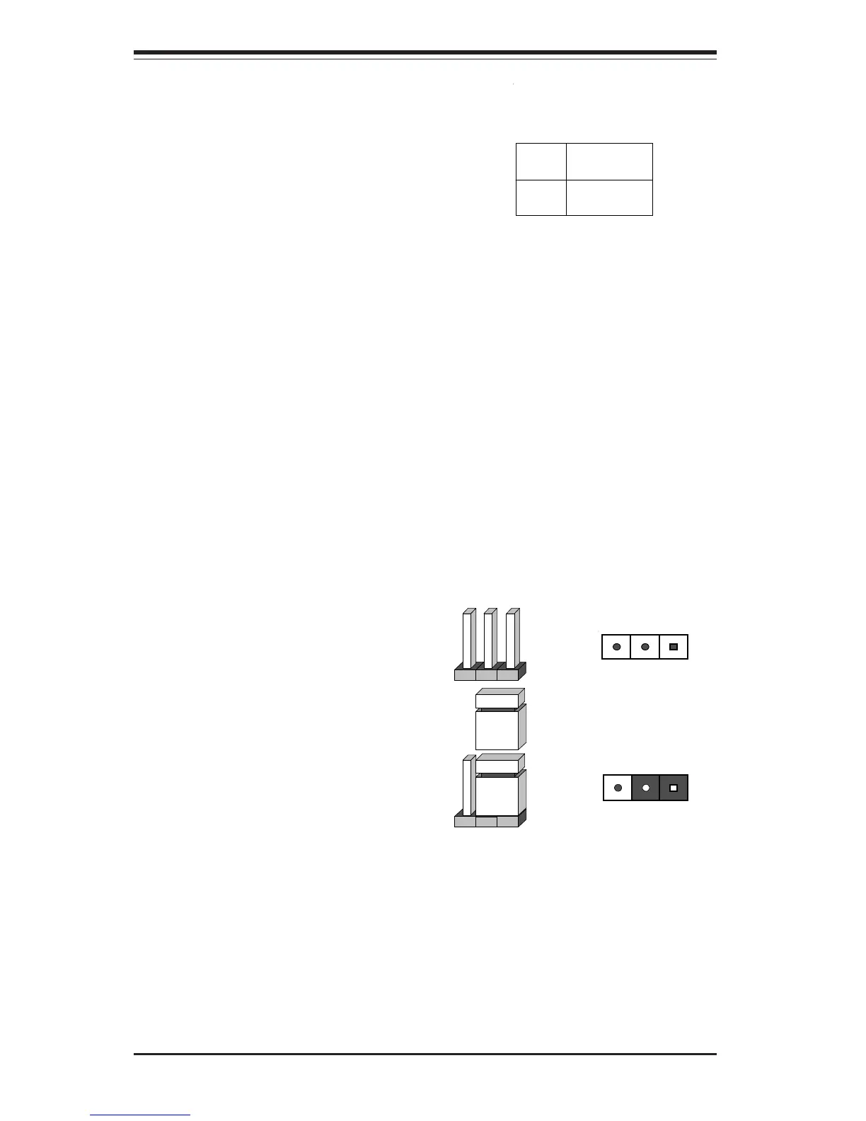
2-7 Jumper Settings
Explanation of
Jumpers
To modify the operation of the
motherboard, jumpers can be used
to choose between optional set-
tings. Jumpers create shorts be-
tween two pins to change the func-
tion of the connector they are lo-
cated on. Pin 1 isalways identi-
fied with a square solder pad on
the printed circuit board. See the
motherboard layout pages for
jumper locations.
Connector
Pins
Jumper
Cap
Settin
Pin 1-2 short
3 2 1
3 2 1
Wake-On-Ring
The Wake-On-Ring header is desig-
nated as JWOR on the P4DC6/P4DC6+/
P4DC6+II/P4DCE/P4DCE+/P4DCE+II.
This function allows your computer to
receive and be "awakened" by an in-
coming call when in the suspend state.
Refer to Table 2-24 for pin definitions.
You must also have a WOR card and
cable to use WOR.
Pin
Number
1
2
Definition
Ground
Wake-up
Table 2-24
Wake-On-Ring Pin
Definitions (JWOR)