Chapter 2: Installation
2-7
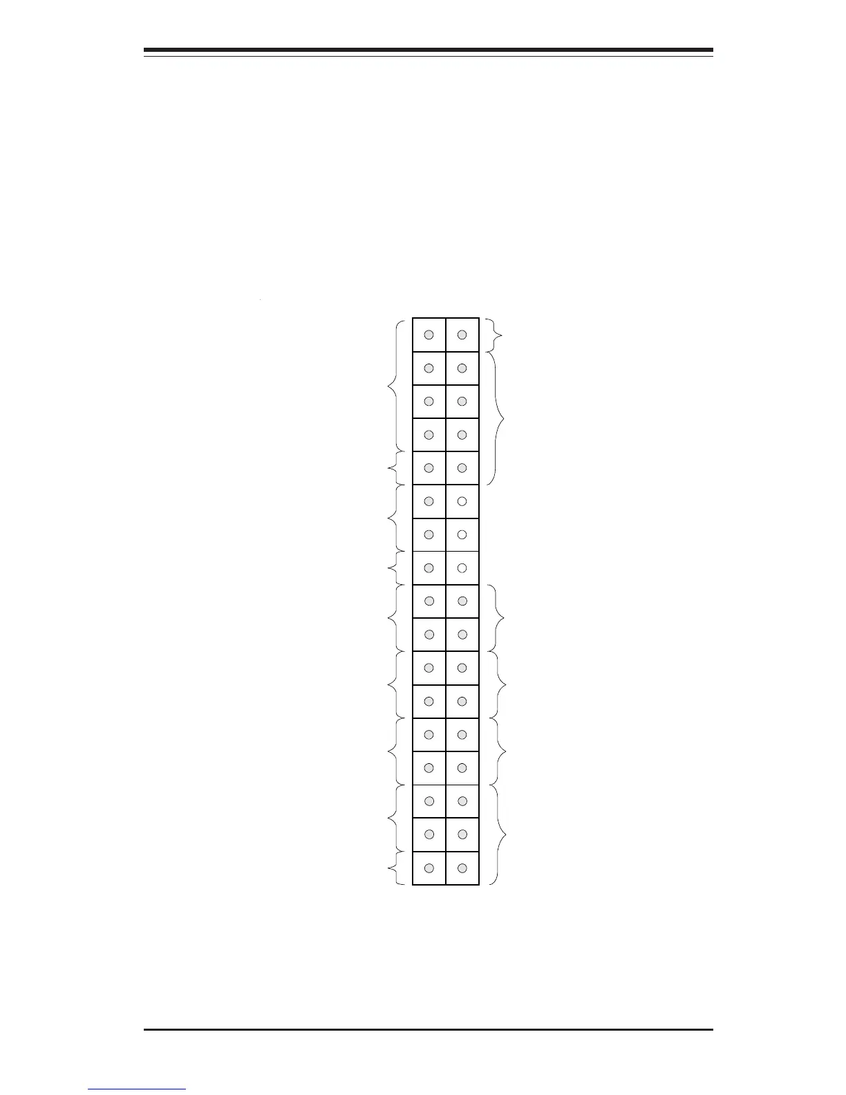
Front Control Panel
JF1 contains header pins for various front control panel connectors. See
Figure 2-5 for the pin locations of the Power LED, IDE LED, Power On,
Reset, USB Keyboard, the 5v System Bus, Fan Failure LED, Power Failure
LED, Network Interface Card LED, I2C LED, Chassis Intrusion, Keyboard
Lock, Overheat and Speaker headers, which are all located on JF1. Refer
to the following section for details.
Figure 2-5. Front Control Panel Connectors
1
PWR LED
IDE LED
PWR ON
RESET
USB KEY
SPEAKER
OVERHEAT
KEYBOARD LOCK
CHASSIS INTRUSION
I
2
C
NIC LED
POWER FAIL LED
FAN FAIL LED
5v STANDBY
JF1
X
X
X
34 33
2
ALARM
RESET