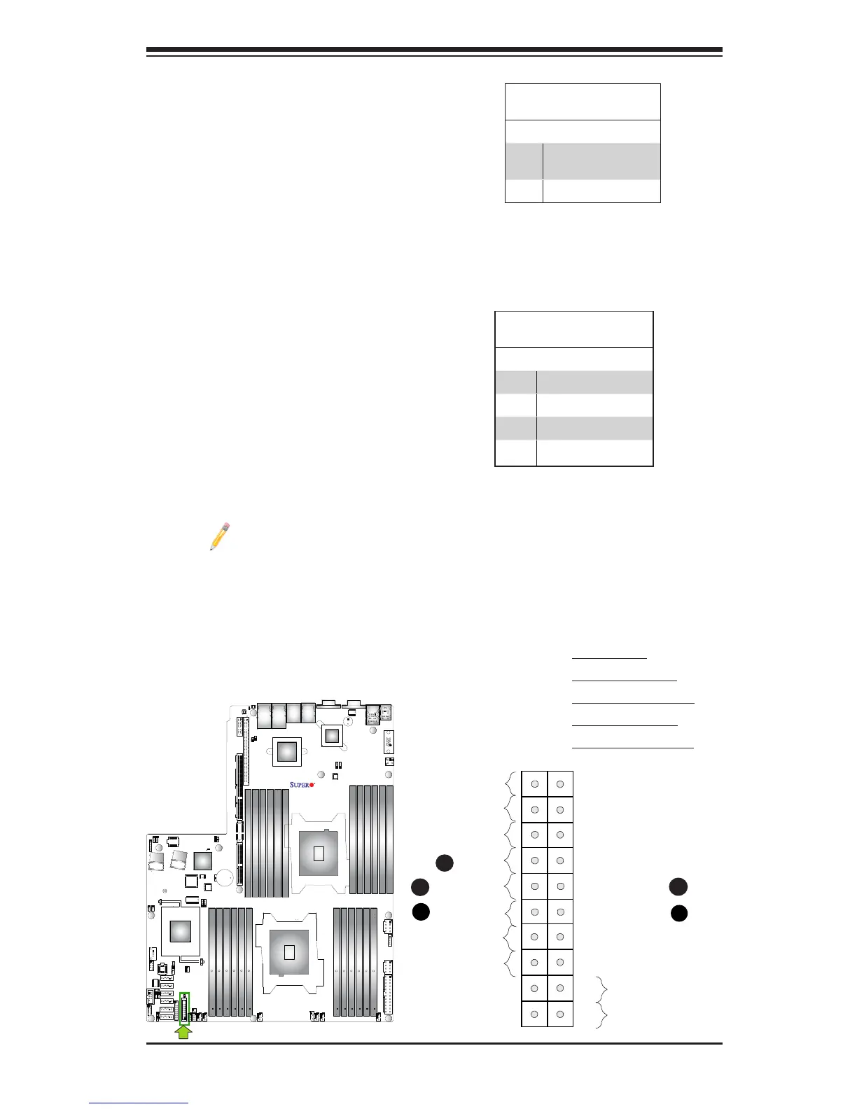
NIC1/NIC2 LED Indicators
The NIC (Network Interface Control-
ler) LED connections for GLAN port 1
are located on pins 11 and 12 of JF1,
and the LED connection for GLAN
Port 2 are on Pins 9 and 10. Attach
the NIC LED cables here to display
network activity. Refer to the table on
the right for pin denitions.
Note: The NIC LED con-
nections for 10G_LAN Ports
3/4 are located on JF2. See
Page 3-27 for details.
HDD LED
The HDD LED connection is located
on pins 13 and 14 of JF1. Attach a
cable here to indicate HDD activ-
ity. See the table on the right for pin
denitions.
HDD LED
PinDenitions(JF1)
Pin# Denition
13 ID_UID_
SW_3.3V/3.3V SB
14 HDD Active
A. HDD LED
B. NIC1 Link LED
C. NIC1 Activity LED
D. NIC2 Link LED
E. NIC2 Activity LED
GLAN1/2 LED
PinDenitions(JF1)
Pin# Denition
9 NIC 2 Activity LED
10 NIC 2 Link LED
11 NIC 1 Activity LED
12 NIC 1 Link LED
X9DRW-3LN4F+
Rev. 1.20