SXB1_3
SXB1_4
1
JUIDB1
CPU2_PORT2C
CPU2_PORT2A
CPU1_PORT2CCPU1_PORT2A
CPU1_PORT3C
CPU1_PORT3A
SXB1D
SXB1C
SXB1B
SXB2
SXB1A
P2-DIMME1
JPW4
CPU2_PORT3D
CPU2_PORT3C
CPU2_PORT3B
CPU2_PORT3A
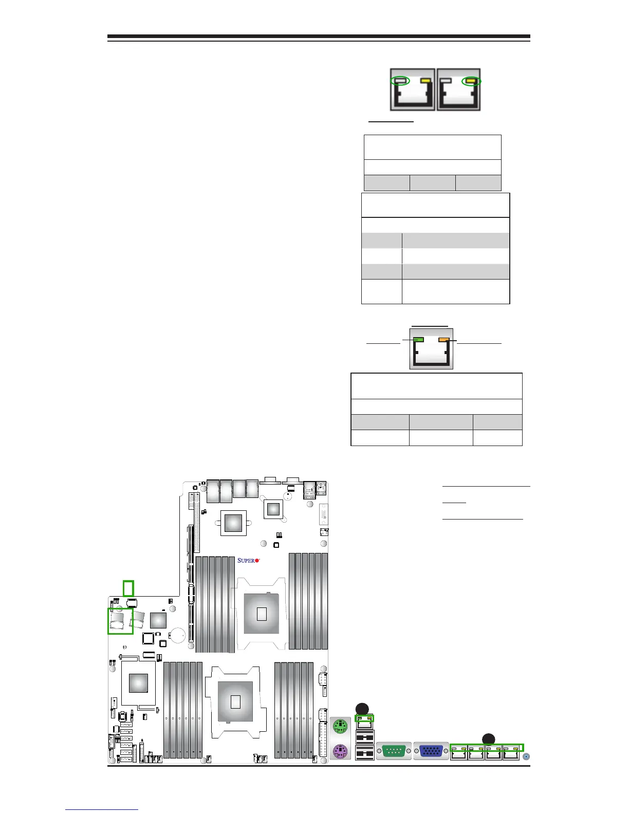
2-8 Onboard LED Indicators
A. Ethernet Port
LEDs
B. IPMI LAN LEDs
IPMI Dedicated LAN LEDs
In addition to the Gigabit Ethernet ports,
an IPMI Dedicated LAN is also located
above the Backplane USB ports 0/1 on the
motherboard. The amber LED on the right
indicates activity, while the green LED on
the left indicates the speed of the con-
nection. See the tables at right for more
information.
Link LED
Activity LED
IPMI LAN
IPMI LAN Link LED (Left) &
Activity LED (Right)
Color/State Denition
Link (Left) Green: Solid 100 Mbps
Activity (Right) Amber: Blinking Active
GLAN LEDs
The LAN 1/2 and 3/4 ports are located on
the IO Backplane. Please note that LAN3/
LAN4 support 10GLAN connections on the
X9DRW-3TF+, and support 1 GLAN for the
X9DRW-3LN4F+. Each Ethernet LAN port
has two LEDs. The yellow LED on the right
indicates activity. The Link LED on the left
may be green, amber or off to indicate the
speed. However, when LAN 1~4 ports are all
used for 1 GLAN connections, the link LEDs
on the left will be green. See the tables at
right for more information.
Activity LED
GLAN Link Indicator
LED Settings
LED Color Denition
Off No Connection or 10 Mbps
Green 100 Mbps
Amber 1 Gbps
Green 1 Gbps (when LAN 1~4 are
all used for 1G connections.
Link LED
GLAN Activity Indicator (Left)
LED Settings
Color Status Denition
Yellow Flashing Active
Rear View (when facing the
rear side of the chassis)
A
B