EasyManua.ls Logo

Supero X9SCAA - Connectors and I;O Ports; Back Panel Connectors and I;O Ports

Supero X9SCAA
87 pages
To Next Page IconTo Next Page
To Previous Page IconTo Previous Page
Loading...
2-6
X9SCAA Motherboard Series User's Manual
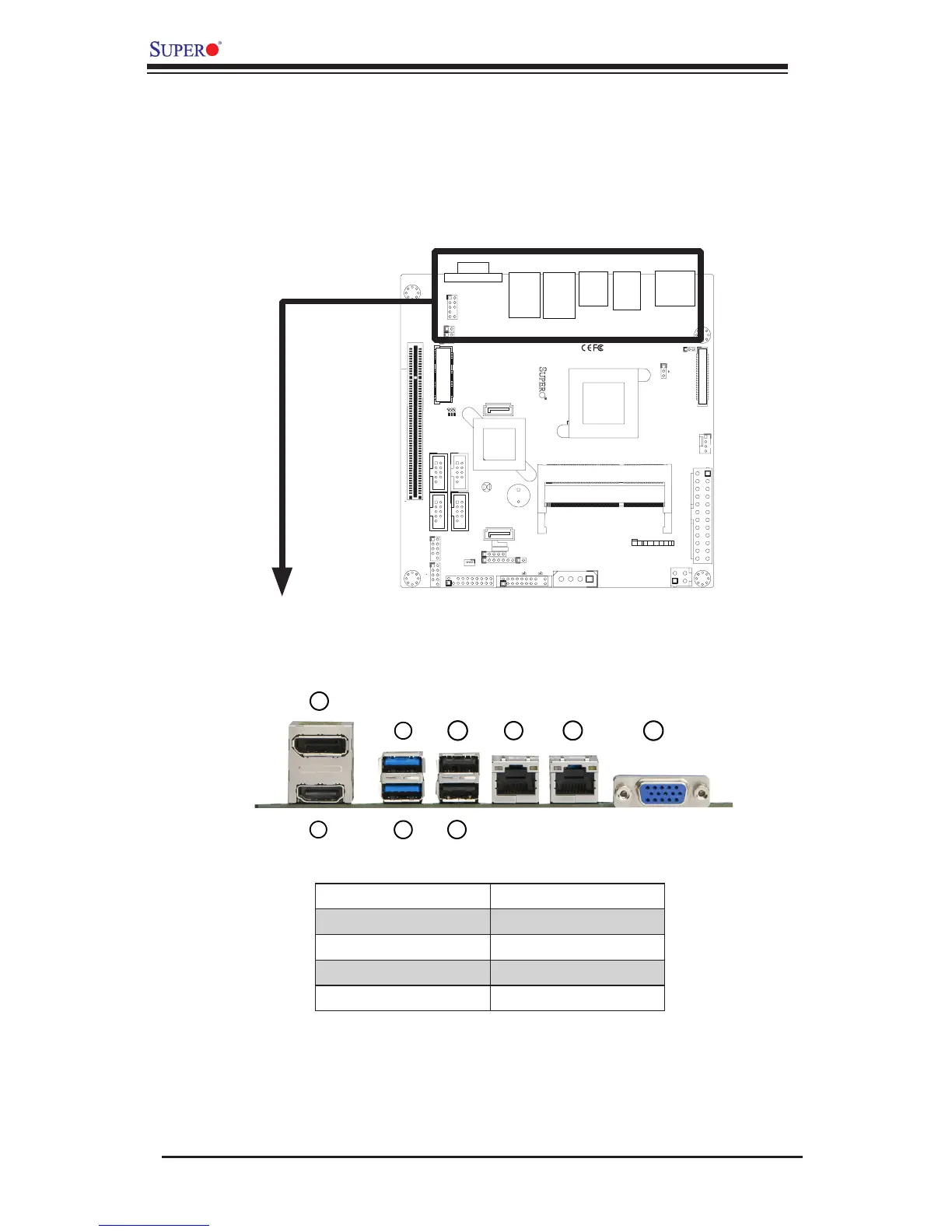
I/O Port Locations and Denitions
2-4 Connectors and I/O Ports
The I/O ports are color coded in conformance with the PC 99 specication. See the
gure below for the colors and locations of the various I/O ports.
Back Panel Connectors and I/O Ports
2
4
7
1
3
5
6
8
1
J1
14
PJ1
1
3
4
JF1
1
2
19
20
JTPM12
19
20
1
JOH1
1
JSPDIF_IN
1
JSPDIF_OUT
JPUSB1
1
JPAC1
1
3
JLCDVCC1
1
JD1
1
JVGA1
11
5
15
6
FAN1
1
4
I-SATA1
I-SATA0
1
2
J2
10
2
7
J7
2
10
J8
7
1
6
9
COM3
COM2COM1
9
1
5
COM4
U10
+
SP1
+
1
JSD1
JBT1
74 72
JDIMM1
2
74
73
71
72
JDIMM2
1
2
A
LED4
C
A
LED3
C
A
LED2
C
CA CA
PRT1
+
U14
DESIGNED IN USA
JPW1
1
(Install rst)
X
Non ECC DDRIII Required
SLOT1 PCI 33MHZ
SATA DOM POWER
JOH1:
OVERHEAT LED
4-7:SPEAKER
1-3:PWR LED
JD1:
LED
SUSPEND
MINI PCIE
LVDS
2-3:LCDVCC P3V3 DEFAULT
1-2:LCDVCC P5V
JLCDVCC
TPM/PORT80
CHASSIS INTRUSION
JL1
JTPM1:
AUDIO FP
USB0/1
USB2/3
1-2:ENABLE
2-3:DISABLE
VGA
JPAC1:ONBOARD AUDIO
LAN2
SODIMM2
SODIMM1
LAN1
USB4/5
PWR
ON
JF1:
RSTOH
FF
X
CPU
USB6/7(3.0)
NIC2 NIC1
HDD
LED
PWR
LED
X
HDMI/DP
Back Panel Connectors
6
1. HDMI* 6. USB3
2. VESA DisplayPort* 7. LAN1
3. USB7 (USB 3.0)* 8. LAN2
4. USB6 (USB 3.0)* 9. VGA Port
5. USB4
* for X9SCAA only

Table of Contents

Related product manuals