Chapter 2: Installation
2-21
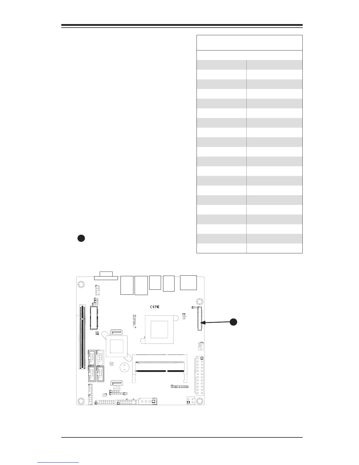
LVDS header
Low-Voltage Differential Signaling (LVDS)
is an industry-standard electrical signaling
system. This signaling system can run at
very high speeds over inexpensive copper
wires using low power.
The LVDS bus on the X9SCAA mother-
board is used to transport video data from
the built-in graphics engine to a compat-
ible LCD display. Please see the table on
the right for pin denitions.
X9SCAA motherboard series supports a
single channel LVDS with 18 & 24 bpps
color depth.
1
J1
14
PJ1
1
3
4
JF1
1
2
19
20
JTPM12
19
20
1
JOH1
1
JSPDIF_IN
1
JSPDIF_OUT
JPUSB1
1
JPAC1
1
3
JLCDVCC1
1
JD1
1
JVGA1
11
5
15
6
FAN1
1
4
I-SATA1
I-SATA0
1
2
J2
10
2
7
J7
2
10
J8
7
1
6
9
COM3
COM2COM1
9
1
5
COM4
U10
+
SP1
+
1
JSD1
JBT1
74 72
JDIMM1
2
74
73
71
72
JDIMM2
1
2
A
LED4
C
A
LED3
C
A
LED2
C
CA CA
PRT1
+
U14
DESIGNED IN USA
JPW1
1
(Install rst)
X
Non ECC DDRIII Required
SLOT1 PCI 33MHZ
SATA DOM POWER
JOH1:
OVERHEAT LED
4-7:SPEAKER
1-3:PWR LED
JD1:
LED
SUSPEND
MINI PCIE
LVDS
2-3:LCDVCC P3V3 DEFAULT
1-2:LCDVCC P5V
JLCDVCC
TPM/PORT80
CHASSIS INTRUSION
JL1
JTPM1:
AUDIO FP
USB0/1
USB2/3
1-2:ENABLE
2-3:DISABLE
VGA
JPAC1:ONBOARD AUDIO
LAN2
SODIMM2
SODIMM1
LAN1
USB4/5
PWR
ON
JF1:
RSTOH
FF
X
CPU
USB6/7(3.0)
NIC2 NIC1
HDD
LED
PWR
LED
X
HDMI/DP
A
LVDS Header
A
LVDS Header
Pin Denitions
Pin # Denition Pin # Denition
1 +12V 2 +12V
3 +12V 4 +12V
5 +12V 6 GND
7 +5V 8 GND
9 LCDVCC 10 LCDVCC
11 DDC CLK 12 DDC DATA
13 BKLTCTL 14 VDD ENABLE
15 BKLTEN 16 GND
17 LVDS A0- 18 LVDS A0+
19 LVDS A1- 20 LVDS A1+
21 LVDS A2- 22 LVDS A2+
23 LVDS ACLK- 24 LVDS ACLK+
25 LVDS A3- 26 LVDS A3+
27 GND 28 GND
29 LVDS B0- 30 LVDS B0+
31 LVDS B1- 32 LVDS B1+
33 LVDS B2- 34 LVDS B2+
35 LVDS BCLK- 36 LVDS BCLK+
37 LVDS B3- 38 LVDS B3+
39 GND 40 GND