2-4
X9SCAA Motherboard Series User's Manual
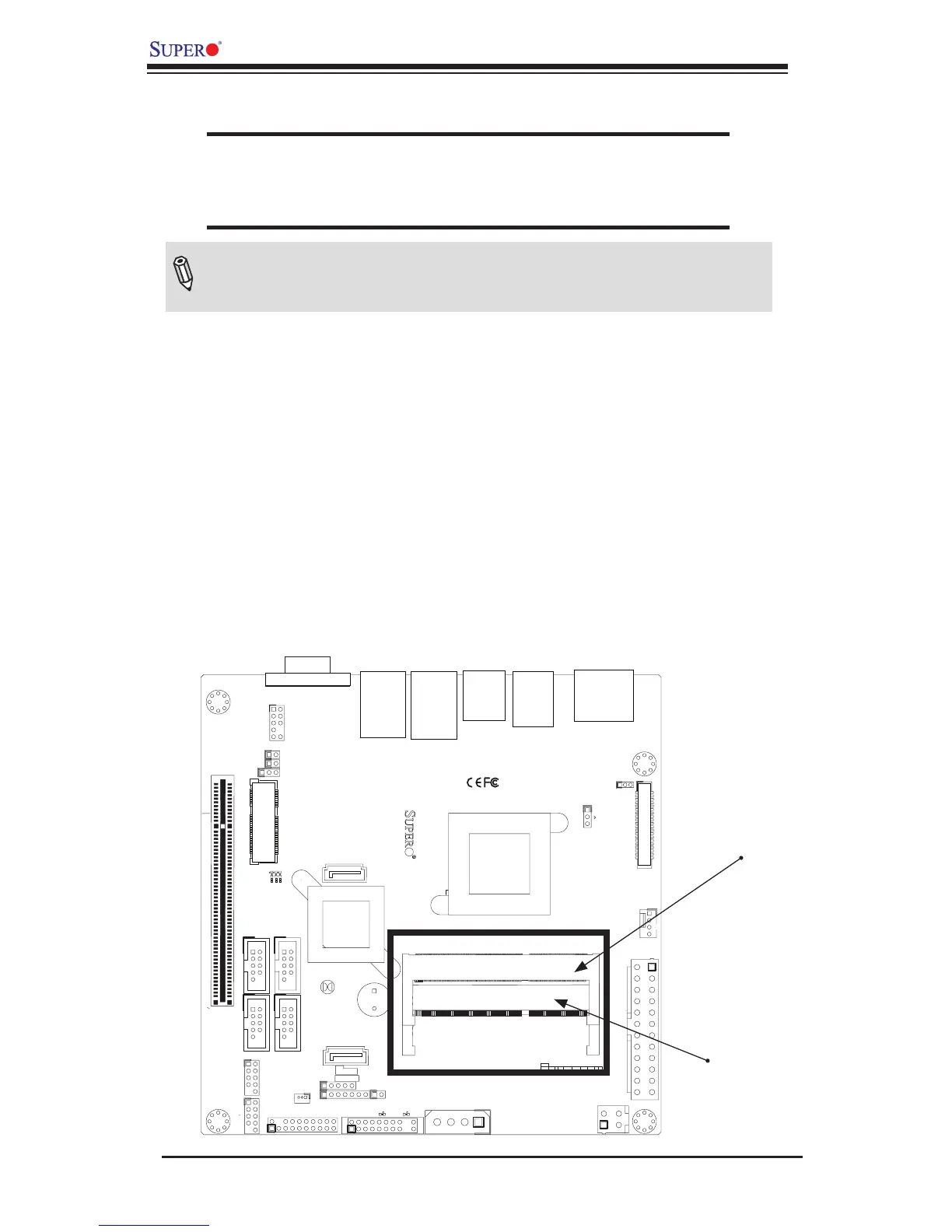
Installing and Removing DIMMs
1
J1
14
PJ1
1
3
4
JF1
1
2
19
20
JTPM12
19
20
1
JOH1
1
JSPDIF_IN
1
JSPDIF_OUT
JPUSB1
1
JPAC1
1
3
JLCDVCC1
1
JD1
1
JVGA1
11
5
15
6
FAN1
1
4
I-SATA1
I-SATA0
1
2
J2
10
2
7
J7
2
10
J8
7
1
6
9
COM3
COM2COM1
9
1
5
COM4
U10
+
SP1
+
1
JSD1
JBT1
74 72
JDIMM1
2
74
73
71
72
JDIMM2
1
2
A
LED4
C
A
LED3
C
A
LED2
C
CA CA
PRT1
+
U14
DESIGNED IN USA
JPW1
1
(Install rst)
X
Non ECC DDRIII Required
SLOT1 PCI 33MHZ
SATA DOM POWER
JOH1:
OVERHEAT LED
4-7:SPEAKER
1-3:PWR LED
JD1:
LED
SUSPEND
MINI PCIE
LVDS
2-3:LCDVCC P3V3 DEFAULT
1-2:LCDVCC P5V
JLCDVCC
TPM/PORT80
CHASSIS INTRUSION
JL1
JTPM1:
AUDIO FP
USB0/1
USB2/3
1-2:ENABLE
2-3:DISABLE
VGA
JPAC1:ONBOARD AUDIO
LAN2
SODIMM2
SODIMM1
LAN1
USB4/5
PWR
ON
JF1:
RSTOH
FF
X
CPU
USB6/7(3.0)
NIC2 NIC1
HDD
LED
PWR
LED
X
HDMI/DP
2-3 System Memory
CAUTION
Exercise extreme care when installing or removing DIMM
modules to prevent any possible damage.
How to Install SODIMMs
1. Insert the desired number of SODIMMs into the memory slots, starting with
SODIMM2, then SODIMM1. Pay attention to the notch along the bottom of
the module to prevent incorrect DIMM module installation.
2. Insert each DIMM module at an angle and snap it into place. Repeat step 1
to install SODIMM1 if needed. See instructions on the next page.
Memory Support
The X9SCAA Motherboard Series supports up to 4GB (2 x 2GB) of unbuffered
Non-ECC DDR3 1066MHz SODIMMs in two low-prole horizontal slots.
Note: Check the Supermicro website for a list of memory modules that
have been validated with the X9SCAA motherboard series.
SODIMM1
SODIMM2