Chapter 2: Installation
2-23
1
J1
14
PJ1
1
3
4
JF1
1
2
19
20
JTPM12
19
20
1
JOH1
1
JSPDIF_IN
1
JSPDIF_OUT
JPUSB1
1
JPAC1
1
3
JLCDVCC1
1
JD1
1
JVGA1
11
5
15
6
FAN1
1
4
I-SATA1
I-SATA0
1
2
J2
10
2
7
J7
2
10
J8
7
1
6
9
COM3
COM2COM1
9
1
5
COM4
U10
+
SP1
+
1
JSD1
JBT1
74 72
JDIMM1
2
74
73
71
72
JDIMM2
1
2
A
LED4
C
A
LED3
C
A
LED2
C
CA CA
PRT1
+
U14
DESIGNED IN USA
JPW1
1
(Install rst)
X
Non ECC DDRIII Required
SLOT1 PCI 33MHZ
SATA DOM POWER
JOH1:
OVERHEAT LED
4-7:SPEAKER
1-3:PWR LED
JD1:
LED
SUSPEND
MINI PCIE
LVDS
2-3:LCDVCC P3V3 DEFAULT
1-2:LCDVCC P5V
JLCDVCC
TPM/PORT80
CHASSIS INTRUSION
JL1
JTPM1:
AUDIO FP
USB0/1
USB2/3
1-2:ENABLE
2-3:DISABLE
VGA
JPAC1:ONBOARD AUDIO
LAN2
SODIMM2
SODIMM1
LAN1
USB4/5
PWR
ON
JF1:
RSTOH
FF
X
CPU
USB6/7(3.0)
NIC2 NIC1
HDD
LED
PWR
LED
X
HDMI/DP
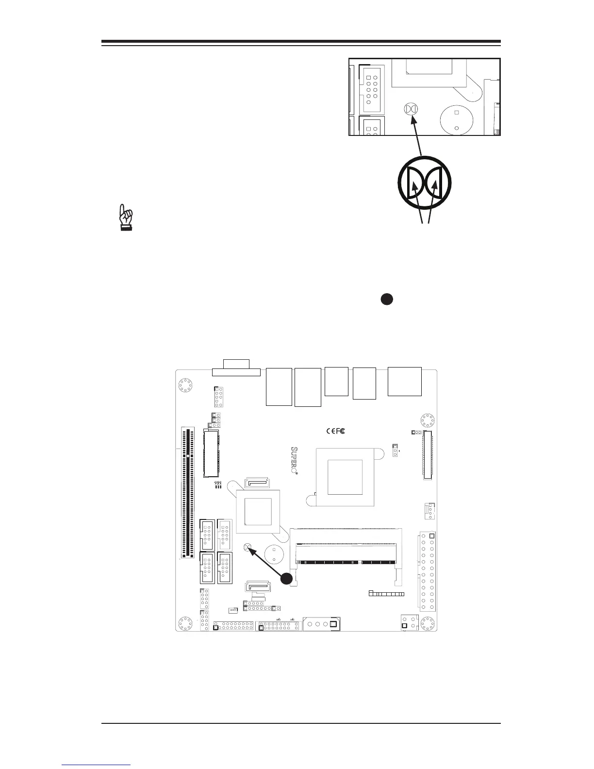
CMOS Clear
JBT1 is used to clear CMOS. Instead of pins,
this "jumper" consists of contact pads to pre-
vent accidental clearing of CMOS. To clear
CMOS, use a metal object such as a small
screwdriver to touch both pads at the same
time to short the connection. Always remove
the AC power cord from the system before
clearing CMOS.
Important: For an ATX power supply, you
must completely shut down the system,
remove the AC power cord and then short
JBT1 to clear CMOS.
A
A
CMOS Clear