EasyManuals Logo

Supero X9SCAA User Manual

Supero X9SCAA
87 pages
To Next Page IconTo Next Page
To Previous Page IconTo Previous Page
Page #33 background imageLoading...
Page #33 background image
Chapter 2: Installation
2-7
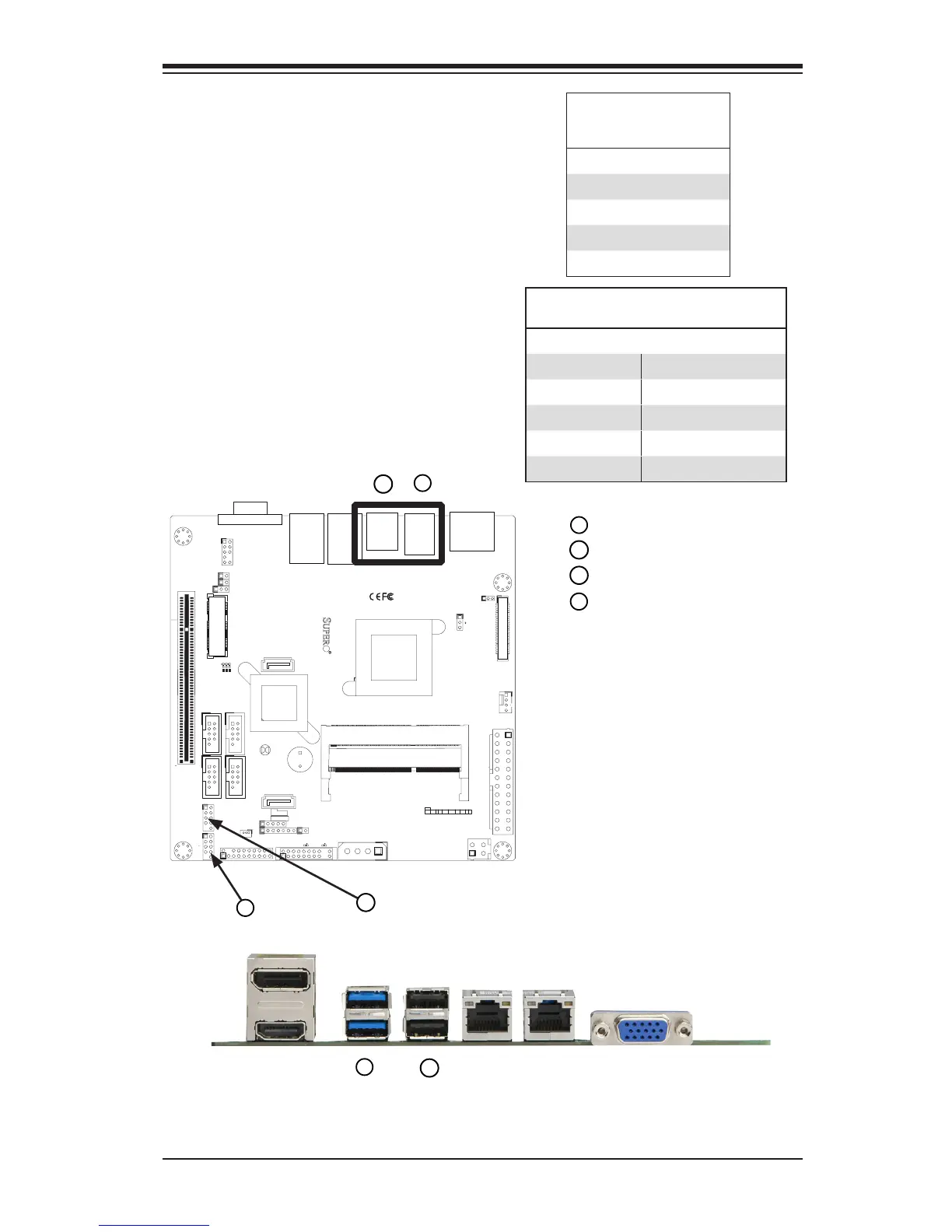
Backpanel USB 6,7 (3.0)*
Backpanel USB 5,4 (2.0)
USB 0/1 header
USB 2/3 header*
Universal Serial Bus (USB 0~7))
Four Universal Serial Bus ports (USB
4,5,6*,7*) are located on the I/O
backpanel. Additionally, four USB ports
(USB 0/1, 2/3*) on 2 headers are also
located on the motherboard to provide
front chassis access. (Cables are not
included). See the tables on the right for
pin denitions.
Back Panel USB
Type A USB
Pin Denitions
Pin# Denition
1 +5V
2 USB_PN
3 USB_PP
4 Ground
Front Panel USB Headers
Pin Denitions
Pin # Denition Pin # Denition
1 5V 2 5V
3 USB_N1 4 USB_N2
5 USB_P1 6 USB_P2
7 Ground 8 Ground
9 Key 10 OC#
3
1
2
1
2
1
J1
14
PJ1
1
3
4
JF1
1
2
19
20
JTPM12
19
20
1
JOH1
1
JSPDIF_IN
1
JSPDIF_OUT
JPUSB1
1
JPAC1
1
3
JLCDVCC1
1
JD1
1
JVGA1
11
5
15
6
FAN1
1
4
I-SATA1
I-SATA0
1
2
J2
10
2
7
J7
2
10
J8
7
1
6
9
COM3
COM2COM1
9
1
5
COM4
U10
+
SP1
+
1
JSD1
JBT1
74 72
JDIMM1
2
74
73
71
72
JDIMM2
1
2
A
LED4
C
A
LED3
C
A
LED2
C
CA CA
PRT1
+
U14
DESIGNED IN USA
JPW1
1
(Install rst)
X
Non ECC DDRIII Required
SLOT1 PCI 33MHZ
SATA DOM POWER
JOH1:
OVERHEAT LED
4-7:SPEAKER
1-3:PWR LED
JD1:
LED
SUSPEND
MINI PCIE
LVDS
2-3:LCDVCC P3V3 DEFAULT
1-2:LCDVCC P5V
JLCDVCC
TPM/PORT80
CHASSIS INTRUSION
JL1
JTPM1:
AUDIO FP
USB0/1
USB2/3
1-2:ENABLE
2-3:DISABLE
VGA
JPAC1:ONBOARD AUDIO
LAN2
SODIMM2
SODIMM1
LAN1
USB4/5
PWR
ON
JF1:
RSTOH
FF
X
CPU
USB6/7(3.0)
NIC2 NIC1
HDD
LED
PWR
LED
X
HDMI/DP
Back Panel Connectors
3
2
1
*X9SCAA only
*X9SCAA only

Table of Contents

Questions and Answers:

Question and Answer IconNeed help?

Do you have a question about the Supero X9SCAA and is the answer not in the manual?

Supero X9SCAA Specifications

General IconGeneral
BrandSupero
ModelX9SCAA
CategoryMotherboard
LanguageEnglish

Related product manuals