Chapter 2: Installation
2-13
Power Button
1
NIC1 LED
Reset Button
2
X
HDD LED
Power LED
#3~4
#1~2
Vcc
Vcc
Vcc
OH/Fan Fail
Ground
Ground
1920
X
X
Vcc
NIC2 LED
X
Vcc
X
X
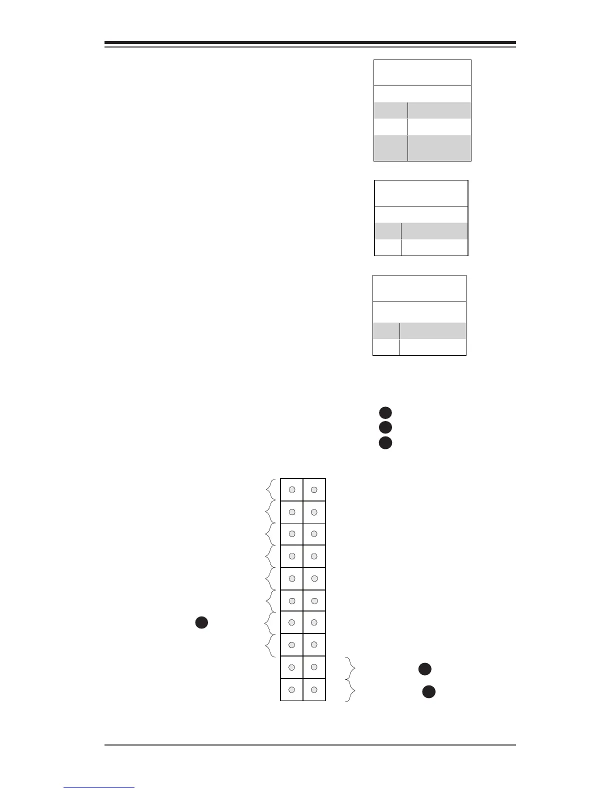
Overheat (OH)/Fan Fail LED
Connect an LED Cable to the OH/Fan
Fail connection on pins 7 and 8 of JF1
to provide advanced warnings of chassis
overheat or fan failure. Refer to the table
on the right for pin denitions.
OH/Fan Fail Indicator
Pin Denitions (JF1)
State Denition
Off Normal
On Overheat
Flash-
ing
Fan Fail
B
JF1 Header Pins
A
B
C
C
Power Button
The Power Button connection is located
on pins 1 and 2 of JF1. Momentarily
contacting both pins will power on/off the
system. To turn off the power when set
to suspend mode, press the button for
at least 4 seconds. Refer to the table on
the right for pin denitions.
Power Button
Pin Denitions (JF1)
Pin# Denition
1 Signal
2 Ground
Reset Button
The Reset Button connection is located
on pins 3 and 4 of JF1. Attach it to a
hardware reset switch on the computer
case. Refer to the table on the right for
pin denitions.
Reset Button
Pin Denitions (JF1)
Pin# Denition
3 Reset
4 Ground
OH/Fan Fail
Reset Button
PWR Button
A