2-14
X9SCAA Motherboard Series User's Manual
1
J1
14
PJ1
1
3
4
JF1
1
2
19
20
JTPM12
19
20
1
JOH1
1
JSPDIF_IN
1
JSPDIF_OUT
JPUSB1
1
JPAC1
1
3
JLCDVCC1
1
JD1
1
JVGA1
11
5
15
6
FAN1
1
4
I-SATA1
I-SATA0
1
2
J2
10
2
7
J7
2
10
J8
7
1
6
9
COM3
COM2COM1
9
1
5
COM4
U10
+
SP1
+
1
JSD1
JBT1
74 72
JDIMM1
2
74
73
71
72
JDIMM2
1
2
A
LED4
C
A
LED3
C
A
LED2
C
CA CA
PRT1
+
U14
DESIGNED IN USA
JPW1
1
(Install rst)
X
Non ECC DDRIII Required
SLOT1 PCI 33MHZ
SATA DOM POWER
JOH1:
OVERHEAT LED
4-7:SPEAKER
1-3:PWR LED
JD1:
LED
SUSPEND
MINI PCIE
LVDS
2-3:LCDVCC P3V3 DEFAULT
1-2:LCDVCC P5V
JLCDVCC
TPM/PORT80
CHASSIS INTRUSION
JL1
JTPM1:
AUDIO FP
USB0/1
USB2/3
1-2:ENABLE
2-3:DISABLE
VGA
JPAC1:ONBOARD AUDIO
LAN2
SODIMM2
SODIMM1
LAN1
USB4/5
PWR
ON
JF1:
RSTOH
FF
X
CPU
USB6/7(3.0)
NIC2 NIC1
HDD
LED
PWR
LED
X
HDMI/DP
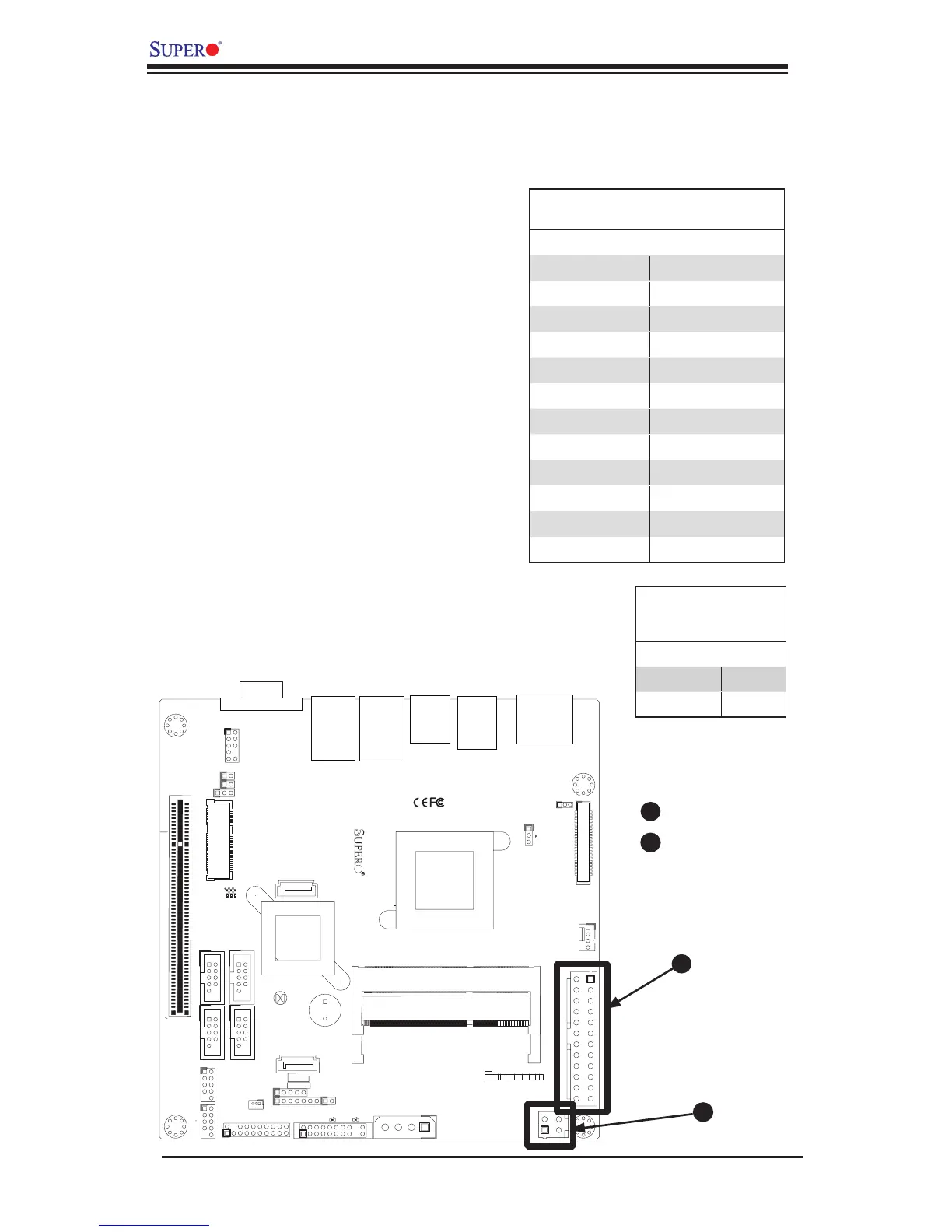
2-5 Connecting Cables
This section provides brief descriptions and pin-out denitions for onboard power
connectors. Be sure to use the correct cable for each header or connector.
24-pin PWR
4-pin PWR
ATX Power 24-pin Connector
Pin Denitions (JPW1)
Pin# Denition Pin # Denition
13 +3.3V 1 +3.3V
14 -12V 2 +3.3V
15 COM 3 COM
16 PS_ON 4 +5V
17 COM 5 COM
18 COM 6 +5V
19 COM 7 COM
20 Res (NC) 8 PWR_OK
21 +5V 9 5VSB
22 +5V 10 +12V
23 +5V 11 +12V
24 COM 12 +3.3V
Power Connectors (JPW1)
The 24-pin (JPW1) power connector
is used to provide power to the moth-
erboard from an ATX power supply.
This connectors meet the SSI EPS 12V
specication. See the tables on the right
for pin denitions.
12V DC only 4-pin Power Connector
(JPW2)
The 4-pin (JPW2) is used for embed-
ded applications with 12V power source
for small enclosures such as the SMC
SC101i chassis.
Note: Either JPW1 or JPW2 may be
used as the main power input, but it is
recommended that only one is actually
connected to the power supply at a time.
B
A
12V 4-pin CPU Power
Connector
Pin Denitions
Pins Denition
1 and 2 Ground
3 and 4 +12V
B
A