Chapter 2: Installation
2-19
1
J1
14
PJ1
1
3
4
JF1
1
2
19
20
JTPM12
19
20
1
JOH1
1
JSPDIF_IN
1
JSPDIF_OUT
JPUSB1
1
JPAC1
1
3
JLCDVCC1
1
JD1
1
JVGA1
11
5
15
6
FAN1
1
4
I-SATA1
I-SATA0
1
2
J2
10
2
7
J7
2
10
J8
7
1
6
9
COM3
COM2COM1
9
1
5
COM4
U10
+
SP1
+
1
JSD1
JBT1
74 72
JDIMM1
2
74
73
71
72
JDIMM2
1
2
A
LED4
C
A
LED3
C
A
LED2
C
CA CA
PRT1
+
U14
DESIGNED IN USA
JPW1
1
(Install rst)
X
Non ECC DDRIII Required
SLOT1 PCI 33MHZ
SATA DOM POWER
JOH1:
OVERHEAT LED
4-7:SPEAKER
1-3:PWR LED
JD1:
LED
SUSPEND
MINI PCIE
LVDS
2-3:LCDVCC P3V3 DEFAULT
1-2:LCDVCC P5V
JLCDVCC
TPM/PORT80
CHASSIS INTRUSION
JL1
JTPM1:
AUDIO FP
USB0/1
USB2/3
1-2:ENABLE
2-3:DISABLE
VGA
JPAC1:ONBOARD AUDIO
LAN2
SODIMM2
SODIMM1
LAN1
USB4/5
PWR
ON
JF1:
RSTOH
FF
X
CPU
USB6/7(3.0)
NIC2 NIC1
HDD
LED
PWR
LED
X
HDMI/DP
B
A
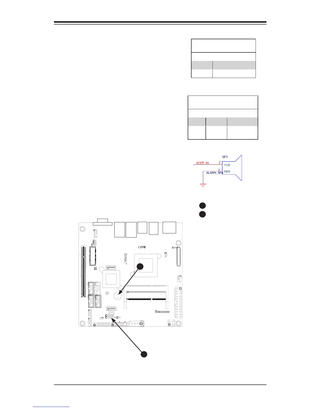
Power LED/Speaker
On the JD1 header, pins 1~3 are used for
a power LED and pins 4~7 are used for
an external speaker. If you wish to use
the onboard speaker, you should close
pins 6-7 with a jumper. See the table on
the right for speaker pin denitions.
Speaker Connector
Pin Denitions
Pin Setting Denition
Pins 6-7 Internal Speaker
Pins 4-7 External Speaker
Internal Speaker/Buzzer
The Internal Speaker on SP1 can be
used to provide audible indications for
various beep codes. See the table on
the right for pin denitions. Refer to
the layout below for the locations of
the Internal Buzzer (SP1).
Internal Buzzer
Pin Denition
Pin# Denitions
Pin 1 Pos. (+) Beep In
Pin 2 Neg. (-) Alarm
Speaker
PWR LED/SPKR
Internal Speaker/Buzzer
A
B