2-18
X9SCAA Motherboard Series User's Manual
1
J1
14
PJ1
1
3
4
JF1
1
2
19
20
JTPM12
19
20
1
JOH1
1
JSPDIF_IN
1
JSPDIF_OUT
JPUSB1
1
JPAC1
1
3
JLCDVCC1
1
JD1
1
JVGA1
11
5
15
6
FAN1
1
4
I-SATA1
I-SATA0
1
2
J2
10
2
7
J7
2
10
J8
7
1
6
9
COM3
COM2COM1
9
1
5
COM4
U10
+
SP1
+
1
JSD1
JBT1
74 72
JDIMM1
2
74
73
71
72
JDIMM2
1
2
A
LED4
C
A
LED3
C
A
LED2
C
CA CA
PRT1
+
U14
DESIGNED IN USA
JPW1
1
(Install rst)
X
Non ECC DDRIII Required
SLOT1 PCI 33MHZ
SATA DOM POWER
JOH1:
OVERHEAT LED
4-7:SPEAKER
1-3:PWR LED
JD1:
LED
SUSPEND
MINI PCIE
LVDS
2-3:LCDVCC P3V3 DEFAULT
1-2:LCDVCC P5V
JLCDVCC
TPM/PORT80
CHASSIS INTRUSION
JL1
JTPM1:
AUDIO FP
USB0/1
USB2/3
1-2:ENABLE
2-3:DISABLE
VGA
JPAC1:ONBOARD AUDIO
LAN2
SODIMM2
SODIMM1
LAN1
USB4/5
PWR
ON
JF1:
RSTOH
FF
X
CPU
USB6/7(3.0)
NIC2 NIC1
HDD
LED
PWR
LED
X
HDMI/DP
A
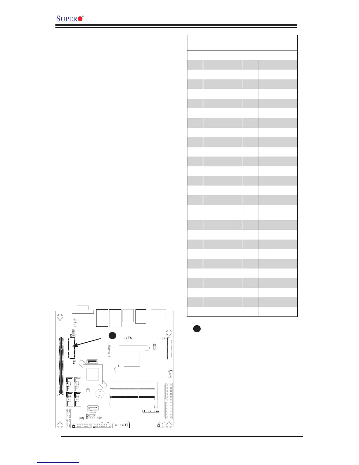
Mini PCI-E Slot (Mini PCIE)
The Mini PCI-E slot is used to install a
compatible Mini PCI-E device. Refer to
the table on right for pin denitions.
The mSATA feature leverages the speed
and reliability of the SATA interface to
provide a high performance, cost-effec-
tive storage solution for smaller devices
like notebooks and netbooks.
The specication maps SATA signals
onto an existing small form factor con-
nector, enabling more compact integra-
tion in a wide variety of applications for
both hard disk (HDD) and solid state
drives (SSDs). The mSATA connector
allows companies to increase the stor-
age offerings of their products without
compromising valuable space.
Mini PCI-E Slot
A
Mini PCI-E
Pin Denitions
Pin# Denition Pin# Denition
51 NC 52 +3.3Vaux
49 NC 50 GND
47 NC 48 +1.5V
45 NC 46 LED_WPAN#
43 NC 44 LED_WLAN#
41 +3.3Vaux 42 LED_WWAN#
39 +3.3Vaux 40 GND
37 GND 38 USB_D+
35 GND 36 USB_D-
33 PETp0 34 GND
31 PETn0 32 SMB_DATA
29 GND 30 SMB_CLK
27 GND 28 +1.5V
25 PERp0 26 GND
23 PERn0 24 +3.3Vaux
21 DET_CARD_
PLUG
22 PERST#
19 NC 20 W_DISABLE#
17 NC 18 GND
15 GND 16 NC
13 REFCLK+ 14 NC
11 REFCLK- 12 NC
9 GND 10 NC
7 CLKREQ# 8 NC
5 NC 6 1.5V
3 NC 4 GND
1 WAKE# 2 3.3Vaux