EasyManuals Logo

Supmeter BST100-B11 User Manual

Supmeter BST100-B11
73 pages
To Next Page IconTo Next Page
To Previous Page IconTo Previous Page
Page #16 background imageLoading...
Page #16 background image
15
4.3 Connection
4.3.1 Loadcell & Speed Sensor Connector (SENSOR)
The shielded cable must be used and kept separate from the AC cable and other noise generating
cables. Please use loadcells with the same capacity, bridge resistance & sensitivity (mV/V) for parallel
connection.
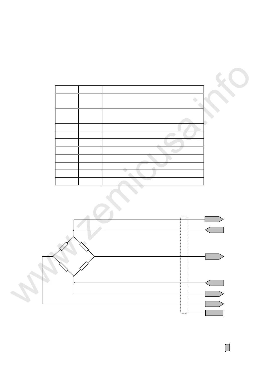
4.3.1.1 Loadcell Connection (SENSOR/LOADCELL)
No.
Pin
Description
1
SEN+
Voltage Feedback + from Loadcell.
[4-wire connection: short to EXC+]
2
SEN-
Voltage Feedback - from Loadcell.
[4-wire connection: short to EXC-]
3
SIG-
Weighing Signal (mV) Input -.
4
SIG+
Weighing Signal (mV) Input +.
5
EXC-
Excitation Voltage Output - for Loadcell.
6
EXC+
Excitation Voltage Output + for Loadcell (DC10V).
7
SHD
Shield.
8
VS-
Voltage Output - for Speed Sensor.
9
SIN
Pulse Signal Input from Speed Sensor.
10
VS+
Voltage Output + for Speed Sensor (DC12V).
SIG+
EXC+
EXC-
SIG-
SIG+
SIG-
SHD
EXC+
EXC-
SEN-
SEN+
SEN+
SEN-
Controller
Loadcell
www.zemicusa.info

Table of Contents

Questions and Answers:

Question and Answer IconNeed help?

Do you have a question about the Supmeter BST100-B11 and is the answer not in the manual?

Supmeter BST100-B11 Specifications

General IconGeneral
BrandSupmeter
ModelBST100-B11
CategoryController
LanguageEnglish

Related product manuals