EMISSION CONTROL INFORMATION 9-7
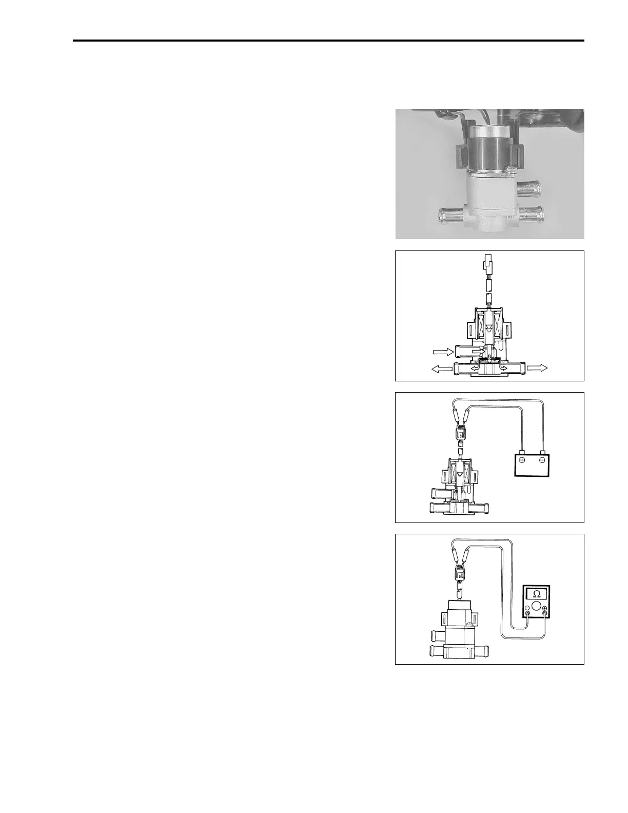
PAIR CONTROL SOLENOID VALVE
(For E-02 and 19)
• Disconnect the PAIR control solenoid valve lead wire coupler.
• Remove the air cleaner box.
• Remove the PAIR control solenoid valve.
• Check that air flows through the air inlet port to the air outlet
ports.
• If air does not flow out, replace the PAIR control solenoid
valve with a new one.
• Connect the 12 V battery to the PAIR control solenoid valve
terminals and check the air flow.
• If air does not flow out, the solenoid valve is in normal condi-
tion.
• Check the resistance between the terminals of the PAIR con-
trol solenoid valve.
! Resistance: 20 – 24 Ω
ΩΩ
Ω (at 20 °C/68 °F)
" 09900-25008: Multi circuit tester set
$ Tester knob indication: Resistance (Ω
ΩΩ
Ω)
If the resistance is not within the standard range, replace the
PAIR control solenoid valve with a new one.
• Connect the PAIR control solenoid valve lead wire coupler
securely.
• Installation is in the reverse order of removal.
Air flow
Air flow
Air flow
Battery

 Loading...