18 A-96.250.111 / 211019
AMI Trides
Installation
3. Installation
3.1. Installation Checklist Monitors
Check Instrument’s specification must conform to your AC power ratings.
Do not turn on power until instructed to do so.
On-site require-
ments
100–240 VAC (± 10%), 50/60 Hz (± 5%) or 24 VDC, isolated
(±10%) power outlet with ground connection and 30 VA.
Sample line with sufficient sample flow and pressure (see Instru-
ment Specification, p. 14.
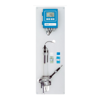
Installation Mount the instrument in vertical position.
Display should be at eye level.
Mount the filter, filter vessel, the long and short overflow tube, the
outer tube and constant head cover
Connect the sample and waste line.
Electrical Wiring Connect all external devices like limit switches, current loops and
pumps (see Connection Diagram, p. 27.)
Connect power cord; do NOT switch on power yet!
Electrodes Install the reference electrode.
Install the pH electrode (optional).
Temperature
sensor
The temperature sensor is already connected to the transmitter
and fixed to the panel with an adhesive tape.
Power-up Turn on the sample flow and wait until the rotor on the Trides sen-
sor starts turning.
Switch on power.
Instrument
set-up
Program all parameters for sensor and external devices (interface,
recorders, etc.).
Program all parameters for instrument operation (limits, alarms).
pH/Redox elec-
trode calibration
Calibrate pH/Redox electrode if installed.
Free chlorine
> 0.1 ppm
Let instrument operate 24 h without interruption at normal sample
conditions. Then correct disinfection value if necessary.
Free chlorine
< 0.1 ppm
Let instrument operate at least 5 days without interruption at
normal sample conditions. Make zero point calibration. Correct
disinfection value if necessary.