AMI Trides
Installation
A-96.250.111 / 211019 29
3.10. Input
NOTICE: Use only potential-free (dry) contacts.
The total resistance (sum of cable resistance and resistance of
the relay contact) must be less than 50 Ω.
Terminals 16/42
For programming see Input 5.3.4, p. 83.
3.11. Relay Contacts
3.11.1 Alarm Relay
NOTICE: Max. load 1 A / 250 VAC
Alarm output for system errors.
Error codes see Troubleshooting, p. 56.
NOTICE: With certain alarms and certain settings of the AMI
transmitter the alarm relay does not switch. The error, however,
is shown on the display.
1) usual use
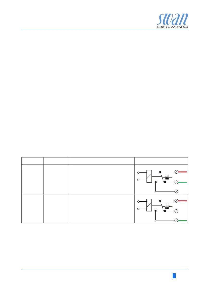
Terminals Description Relay connection
NC
1)
Normally
Closed
10/11 Active (opened) during normal
operation.
Inactive (closed) on error and
loss of power.
NO
Normally
Open
12/11 Active (closed) during normal
operation.
Inactive (opened) on error and
loss of power.