AMI Trides
Maintenance
A-96.250.111 / 211019 49
Disassemble
the flow cell
1 Switch off the instrument.
2 Stop the sample flow at the main tap before the sample inlet.
3 Open the grab sample tap [G] to empty the flow cell.
4 Remove all sensors.
5 Put the rubber cap on the tip of the reference (and pH) elec-
trode and plug cap on sensor plug.
6 Remove the following parts from the flow cell block [F]:
–Constant head cover
–Constant head tube
–Overflow tube long
–Overflow tube short
–O-ring
–Grab sample tap
–Grab sample outlet
–Filter
–Filter vessel
–Sample outlet
–Sample Inlet
–Flow regulating valve
7 Clean all acrylic parts with a soft brush (e.g. a bottle cleaner)
and soapy water. Remove calcareous deposits with a common
household deliming agent with standard concentrations.
8 Clean the bores of the flow cell block with pipe cleaners.
Assemble the
flow cell
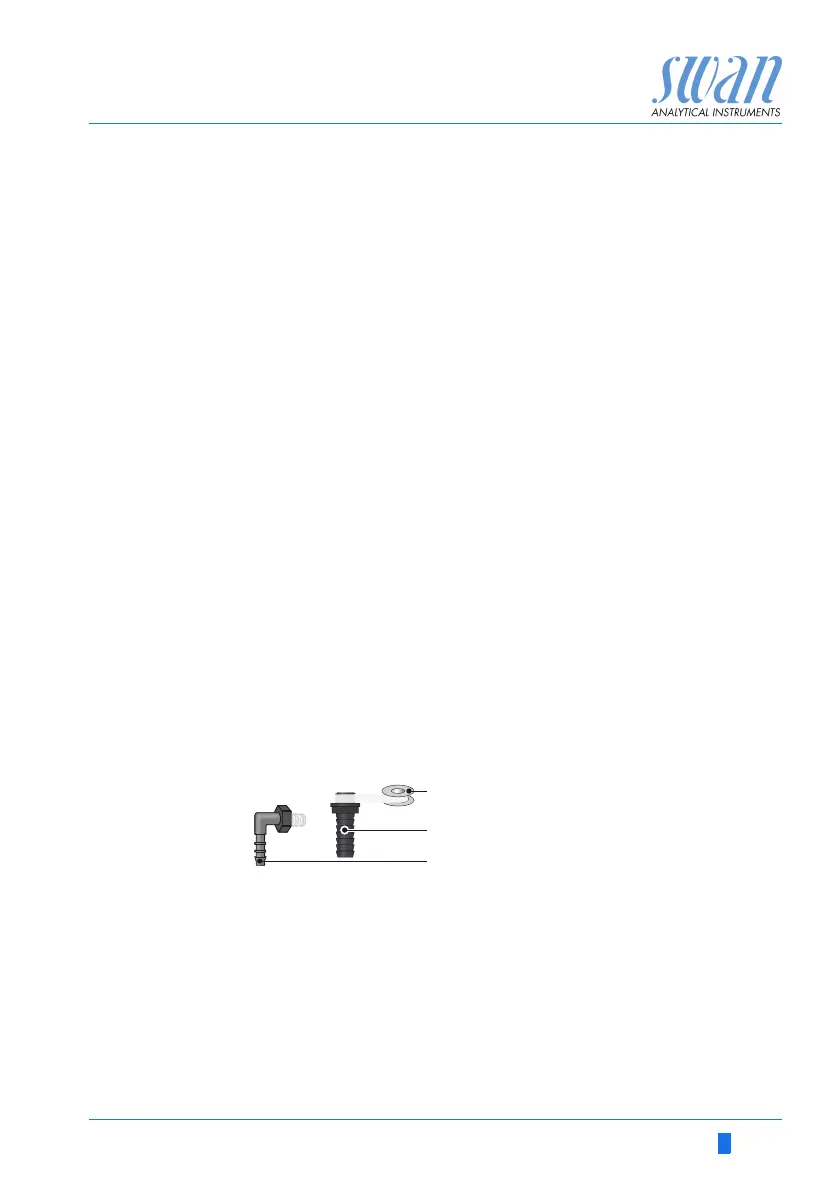
1 Wrap 7 turns of teflon tape around the hose nozzle thread
2 Replace all o-rings and grease them with teflon paste.
3 Assemble the flow cell.
4 Install all sensors.
5 Open the main tap and wait until the flow cell is filled
6 Check all connection for leakage, if necessary retighten leaky
points.
7 Switch on the instrument.
A
B
C
Teflon band
Hose nozzle at sample outlet
Elbow hose nozzle at sample inlet