8. V-Belt Drive System / Kick Starter
8-4
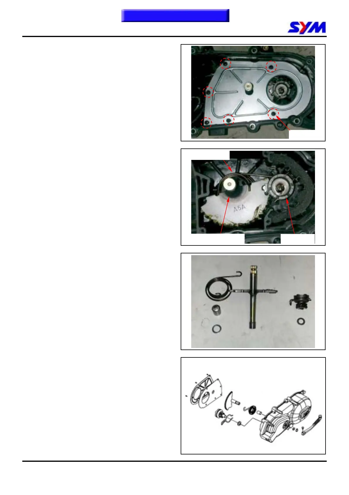
Remove the inner plate inside of left crankcase
cover. (6 screws)
Install kick starter arm, rotate the lever slightly and
then remove driven gear and washer. Remove
the kick starter arm, kick starter spindle, spindle
bush and return spring as well as socket.
Inspection
Check if kick starter spindle, kick spindle bush,
kick driven gear for wear or damage.
Replace it with new one if necessary.
Check the return spring and friction spring for
spring force or damaged.
Replace it with one if poor parts found.
Reassembly
Install socket, return spring and starter shaft as
diagram shown.
Install thrust washer and snap ring onto starter
shaft.
Install kick starter lever temporary.
Rotate the lever and then align driving gear with
width-tooth on the starter shaft.
Install the friction of driving gear onto convex part
of the cover.
Install the left crankcase cover.
6 screws
Kick starter spindle
Driven gear
Return spring
To this cha
ter contents
 Loading...