16. Electrical Equipment
16-22
Switch / Horn
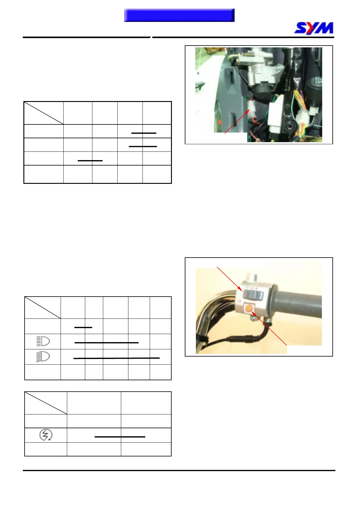
Main Switch
Check
Remove front cover. (3 screws)
Disconnect main switch leads coupler.
Check coupler terminals as following pins for
continuity.
Pin
Location
BAT1 BAT2 IG E
LOCK
● ●
OFF
● ●
ON
● ●
Wire color Red Black
Black/
White
Green
Replacement
Remove main switch cover. (1 screw)
Remove the main switch coupler and bolts (2
bolts)
Remove the main switch.
Install a new main switch and tighten the bolts. (2
bolts)
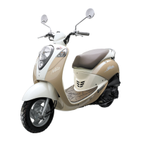
Right Handle Switch
Remove the front cover.
Disconnect the coupler of the handle switch.
Check the continuity of follow pins listed below
columns.
Headlight & Dimmer switch
Pin
Location
CI RE TL LO HI
●
●
●
●
● ●
● ● ●
Wire color Yellow Pink Brown White Blue
Start switch
Pin
Location
ST E
FREE
●
●
Wire color Yellow / Red Green
Main switch coupler
Start switch
Headlight & Dimmer switch
To this chapter contents