TA I
NSTRUMENTS
TGA 2950 2–13
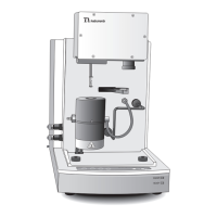
Figure 2.6
TGA 2950
Connector Panel
3. Remove the water lines from the packing.
4. Connect one end of the water line marked
“SUPPLY” to the connector labeled “SUP-
PLY” on the right side of the instrument
cabinet.
5. Connect the other end of the water line
marked “SUPPLY” to the connector labeled
“SUPPLY” on the heat exchanger.
6. Connect one end of the unmarked water line
to the connector labeled “RETURN” on the
right side of the instrument cabinet.
7. Connect the other end of the unmarked
water line to the connector labeled “RE-
TURN” on the heat exchanger.
Installing the Instrument