1
CONTENT
1. Notice before start-up ..................................................................................................3
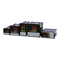
2. FU Series.....................................................................................................................4
2.1 Specifications......................................................................................................4
2.2 Outer Dimension.................................................................................................5
2.3 Terminal Wiring Diagram ....................................................................................6
2.4 Assembly & Wiring .............................................................................................7
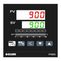
3 FY Series ....................................................................................................................8
4. Terminal arrangement................................................................................................ 11
4.1 FY400 / FU48 Terminals ( 48mm x 48mm , DIN 1/16 )..................................... 11
4.2 FY600 Terminals ( 96mm x 48mm , DIN 1/8 )...................................................12
4.3 FY700 / FU72 Terminals ( 72mm x 72mm) .......................................................13
4.4 FY800 / FU86 Terminals ( 48mm x 96mm , DIN 1/8 ).......................................14
4.5 FY900 / FU96 Terminals ( 96mm x 96mm , DIN 1/4 ).......................................15
4.6 FY100 Terminals ( 175mm x 110mm ) ..............................................................16
4.7 FY101 Terminals ( 90mm x 90mm )..................................................................17
5. External dimension and panel cutout〈Unit:mm〉 .................................................18
5.1 FY100...............................................................................................................18
5.2 FY101...............................................................................................................18
5.3 FY400~900 & FU48~96....................................................................................19
6. Parts description ........................................................................................................20
7. Operations .................................................................................................................21
7.1 Power On..........................................................................................................21
7.2 Change the Set Value (SV)...............................................................................21
7.3 Change the Alarm Value ...................................................................................21
7.4 Autotuning (AT).................................................................................................22
7.5 Programmable RAMP / SOAK (Only available for PFY model) ........................23
8. Operation levels.........................................................................................................24
8.1 Levels diagram .................................................................................................24
8.2 Lock function ....................................................................................................24
9. Parameters ................................................................................................................25
9.1 Level 1 (User Level) .........................................................................................25
9.2 Level 2 (PID Level) ...........................................................................................26
9.2.1 Level 2 parameters display / hiding condition ......................................26
9.2.2 Description of parameters....................................................................27
9.3 Level 3 (Input Level) .........................................................................................28
9.4 Level 4 (SET level) ...........................................................................................30
9.4.1 How to hide parameters (Use SET1~SET7) ........................................30
9.4.2 Special functions (Use SET8 / SET9 / SET0) ......................................31
9.4.3 Remote SV type selection ...................................................................32
9.4.4 Output mode selection (Use OUTY) ....................................................32
9.4.5 Modify caution .....................................................................................32
9.5 Program Level (Only displayed in programmable controller) .........................33
9.5.1 Description of parameters....................................................................33
 Loading...