62
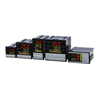
18.11 Wiring diagram of PC communication
PC
COM PORT :
9PIN
( DTE )
SD
SG
RD
Pin 3 (T)
Pin 2 (R)
Pin 5 (G)
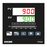
RS232 Connection Diagram
PC
COM PORT :
25PIN
( DTE )
Pin 2 (T)
Pin 3 (R)
Pin 7 (G)
NOTE:
1.The length of cable be connected between controller and PC can't exceed 15 meter.
2.One Com Port can only be connected to one controller.
If more than one controller is connected to one Com Port,communication will be failed.
3.Ensure that the controller's IDNO and BAUD settings are the same with PC software's settings.
4.For the software communication format please refer to communication manual.
SD
SG
RD
Controller
Controller
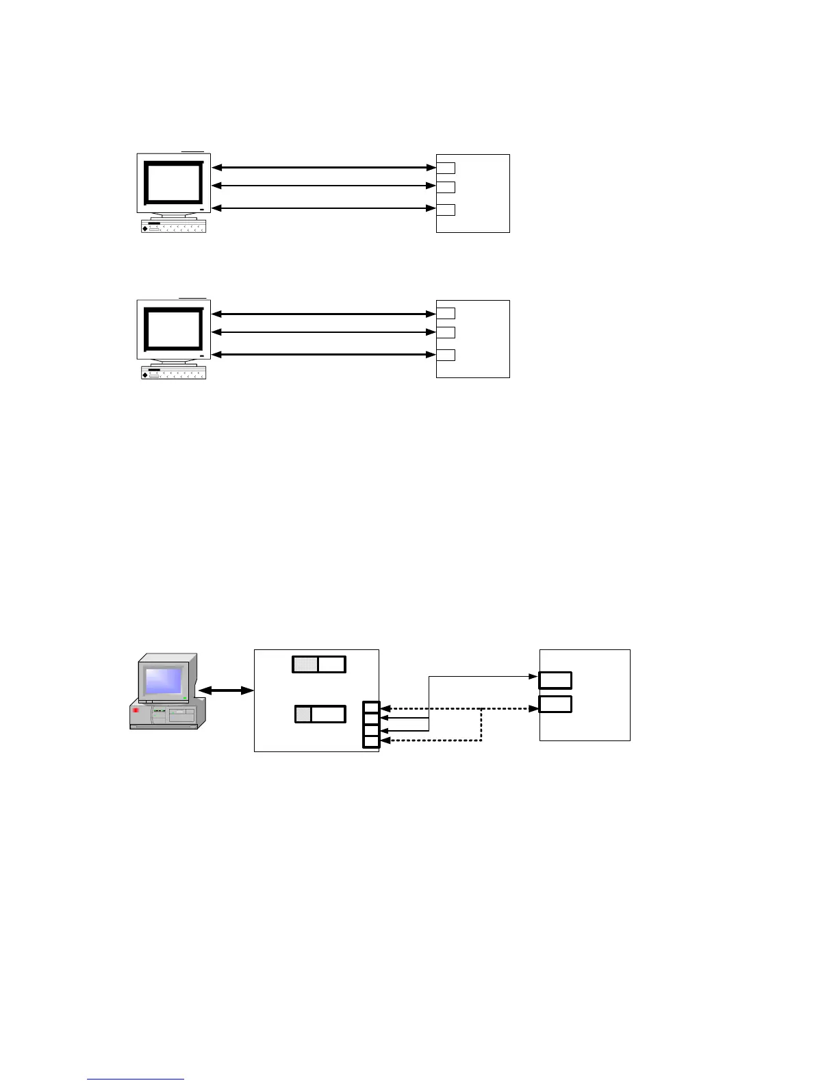
RS485 Connection Diagram
NOTE:
1.The length of cable be connected between Converter and Controller can't exceed 1.2 KM.
Suggestion:choose "Shielded Cable".
2.One Com Port can be connected up to a maximum of 30 Controllers.
3.Ensure that the Controller's IDNO and BAUD settings are the same with PC software's settings.
4.For the software communication format ,please refer to communication manual.
PC
Com Port
(Cable)
Converter
DCE
TxON
RxO
N
Controller
1
2
3
4
DX +
DX -
(R-)
(T-)
(T+)
(R+)
Cable
 Loading...