M8SL2-00-002-812 DC Line Keying G5.1
© Copyright Tait Electronics Limited August 2004. All rights reserved.
5 DC Line Keying
Where the transmitter and receiver are separated by only a short distance and DC isola-
tion is not required, DC loop keying may be employed.
Note: This feature is not available with standard line transformer ETAL P2781
(%T201B). Refer to Section 2.2.
A small DC current (usually less than 10mA) can be fed via the balanced 2-wire line to
provide remote control of various functions.
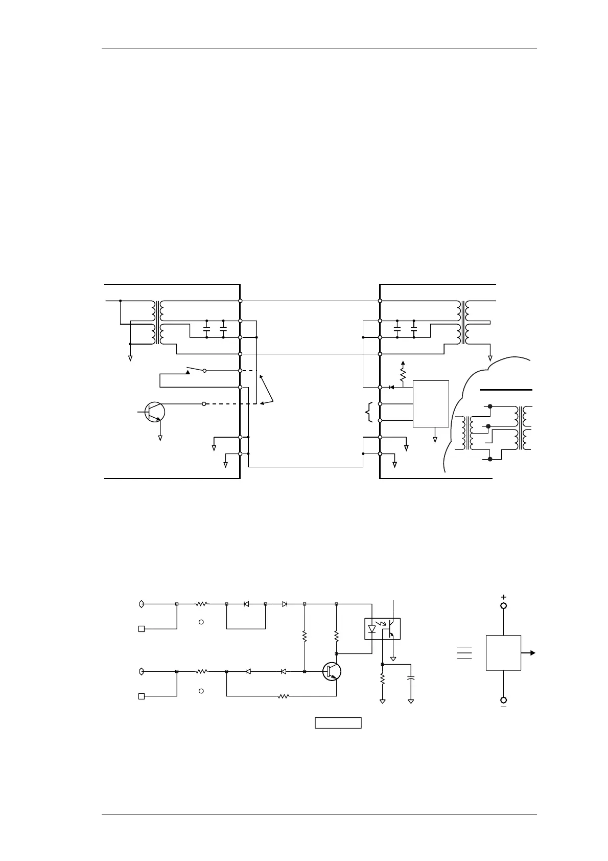
In a duplex system the receiver mute is used to key a transmitter, provided there is a
common earth between the two units (refer to Figure 5.6).
Figure 5.6 DC Loop Keying With Common Earth
Where the receiver and transmitter (or remote control) are distant, DC loop keying is
provided by an isolated supply, driver and detector because an earth cannot be relied on
(refer to Figure 5.7, Figure 5.8 and Figure 5.9).
Figure 5.7 Isolated Constant Current Loop Current Detector
(Opto-key input on T854)
Pin 14
Pin 12
Pin 1 (PL100)
Pin 3
Tx Key Pin 13
Pin 1
Pin 2
Pin 3
Pin 4
Pin 12
Pin 11
Pin 15
Pin 14
C266
8
4
3
5
6
2
7
1
Audio
Out
T210
C268
RL210
Pin 13
C202
1
5
6
4
3
7
2
8
T210
C201
Pin 4 (PL100)
Audio
Processor
Keying
Logic
Pin 15
Earth
Pin 2
+
-
Opto Key
+9V
R657
D620
Optional:
Relay contact or
Q270 collector
can be used.
Receiver Transmitter
Short Line
Q270
T210A/B
1
4
3
2
Transmitter
C201, 202, 230A %R203B/C/D
not shown for clarity
OR
Det.
D260 D260
BAW56
BAW56
23
3
1
I/OPAD
P219
OPTO-KEY+
OPTO-KEY-
OPTO-KEY+
OPTO-KEY-
I/OPAD
P225
D270
D270
BAV99 BAV99
13 3
2
R268
100
OPTO-KEY
Q270
BD139
R271
390K
C275
120P
R269
10K
R270
470
IC250
4N25A
15
2
64
R240
R243

 Loading...


