SERVICE PROCEDURES
SERVICE PROCEDURES
On-Demand Water Heater Service Handbook for 240, 340 & 540 Condensing Models • 41
6.2.4
Once loosened, grasp an
oval air vent in the center
and pull the burner out.
Brace the boom of the
combuson chamber to
provide leverage.
6.3
Inspect the gasket. Minor
surface tears are acceptable.
If the gasket shows major
separaons, replace the
gasket before the unit is
returned to service. (The
parts list starts on page
75; burner assembly
components are idened
on page 73.)
7. Clean the burner with compressed
air and a wire brush.
If necessary, continue according to
these instructions:
•
Use a safe degreaser.
•
Protect the burner gasket from
direct water pressure. If the
gasket is damaged in any way,
contact technical service for
further assistance.
7.1 Saturate the burner with
the cleaning soluon (from
top, down through slots, and
openings in front of burner).
Connue unl burner is
completely wet.
7.2
Wait for ve minutes.
7.3
Set the burner in a sink in its
normal, upright posion and
wash the burner with a high
ow of water. Ensure that
the water ows down into
the slots, starng at the back
and moving forward. Make
sure that no contact is made
with the gasket; protect it
from direct water pressure.
Rinse thoroughly.
7.4
Clear excessive water from the
burner with compressed air.
7.5
Inspect the gasket. Minor
surface tears are acceptable.
If the gasket shows major
separaons, replace the
gasket before the unit is
returned to service.
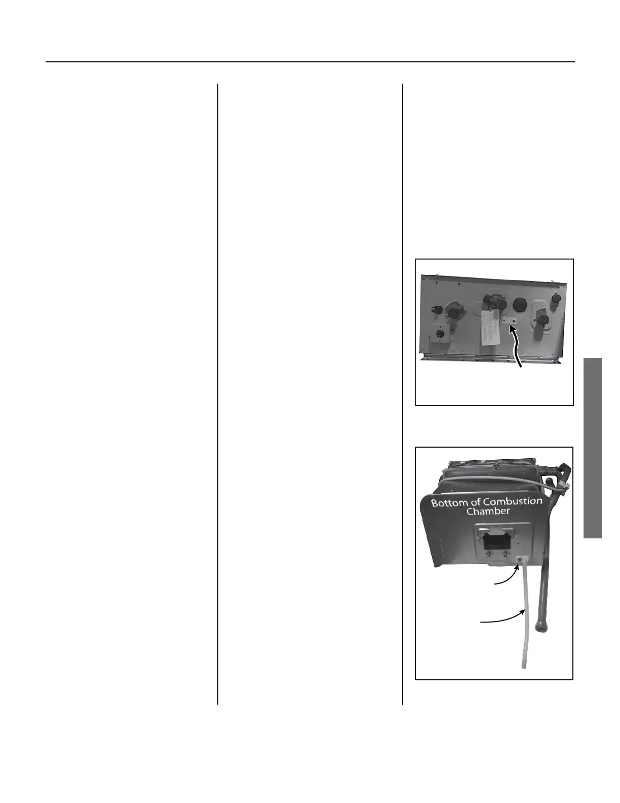
8. Clean the fan:
8.1
Remove the fan from the
boom of the combuson
chamber as follows:
8.1.1
Remove the two Phillips/hex
head screws poinng down
from the fan using an 8”
long, #2 Phillips head screw
driver. There are 2 holes
in the case directly below
the screws to put the screw
driver through (Figure 31).
NOTICE: During the next
step, remove the fan
cauously. Do not allow it
to strike the ow sensor/
control valve during removal.
See
Figure 42 (p. 50).
8.1.2
Slide the fan toward you to
remove it from the rear slots
that hold it in place. Remove
the fan.
8.2
Hold the fan away from the
water heater cabinet.
8.3
Blow compressed air into
the fan. The fan will rotate
and dust will y out of the
fan housing.
NOTE: You will reassemble
these items in reverse order
at the end of this procedure.
Clean the heat exchanger:
9.1 Place a towel at the bottom
of the combustion chamber
so that it covers the fan
discharge opening (fan port).
CAUTION: Wear eye
protection during the
following steps. We also
recommend that you wear a
face mask which covers your
mouth and nose. Failure
to do so could result in
personal injury.
Connector/
Nipple
Air Tube
Figure 32.
Holes (2) for access to fan
screws. Both holes are
located under the tape.
Figure 31.
 Loading...


