10
The buzzer will sound at the startup of the system, it will sound whenever any key of the
keyboard it touched and if requested it will sound while being at the main menu and there exist
alarm events in the system.
The Reset button when pushed will restart the activity of the CPU board, an action that
could be harmful when done by unauthorized people, therefore should be avoided.
When the visibility of the LCD display needs to be improved, the LCD contrast can be adjusted
by using a small screwdriver and turning the screw of the potentiometer (blue component) a
few turns to the right or to the left until the optimal visibility is achieved.
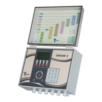
The three Power ON █ █ █ LEDs on the CPU board will turn on while it is energized. The
three Remote I/O communication █ █ █ LEDs will start blinking when the CPU starts
communicating with the peripheral I/O Interfaces.
Notice that:
Each CPU board has its unique ID number of 10 digits by which it is recognized by the
Server. All the data related with the controller is stored under this ID number, therefore if a
CPU board need to be replaced, The Server must by notified (through the
ADMINISTRATION software) about the new CPU that replaces the old one.
2. SWITCHING UP AND SHUTTING DOWN
2.1 Switching Up
Switching up the DREAM 2 from a switched off state is done in 2 steps:
1. Turning ON the Power Switch.
2. Pushing the Start button.
When the DREAM 2 application starts running, a few activities start in parallel:
The LCD display connected to the CPU board will start showing some introductory
screens then the System manager screen (described below) will appear for a few
seconds and eventually the Main menu of the DREAM application will be displayed. The
user should wait patiently until this stage is reached.
The CPU will start scanning all the Interfaces second by second, sending them the
required status of the outputs receiving back the status of the inputs. This activity is
indicated by blinking of the REMOTE I/O communication █ █ █ LEDs on the CPU
Board and the communication LED on each of the Interfaces.
Right after starting up the DREAM 2 application, the controller starts looking for its host
server on the Internet, in order to login to the service.