27
normally closed valves, the position of the black and the red wires should be
interchanged.
Several DC outputs may share one wire as common, this wire will be connected to any
of the terminals on the outputs terminal block marked by the letter “C” which serves as
the outputs common.
Commons of separate I/O boards cannot be interconnected.
The length of the wires from the I/O board to the DC latching device to be activated,
cannot be long, it differs with the type of solenoid used. The correct distance should be
consulted with the manufacturer.
An output remains activated as long as it does not receive the opposite command.
The voltage at the DC output cannot be measured by regular voltmeters because it
exists for a very short period.
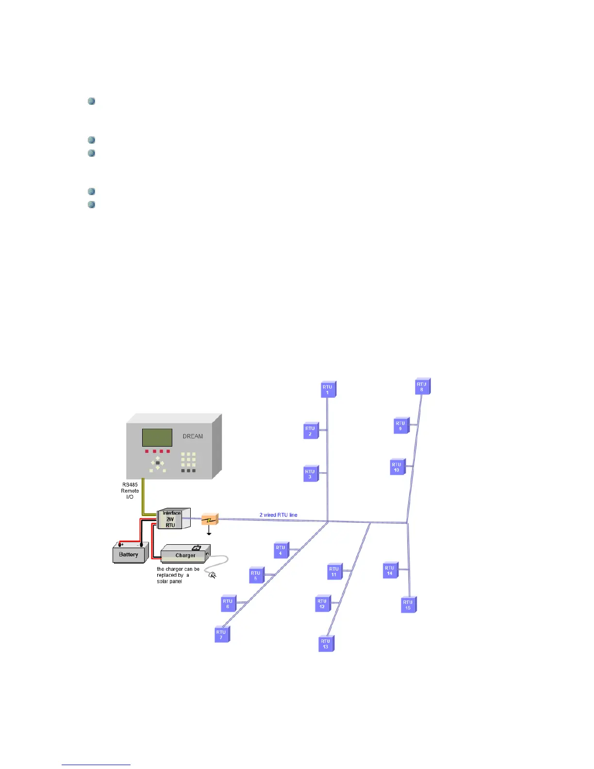
5.2 Interface for single cable 2 wired RTUs
When it is required to reach distant I/O devices (radius of 10 km) and it is possible to lay a 2
wired cable in the field, we shall use the 2 wired RTU system to reach all the remote I/O
devices. The RTUs are Remote Terminal Units, which can read digital or analog inputs and
activate DC latching outputs. The RTUs will be placed wherever there are I/O devices to
control. A 2 wired cable will be running from the 2W interface to the RTUs like branches of a
tree. The 2 wired line is used both for communication and for supplying energy to the RTUs
from the 2W interface. Up to 60 RTUs may be connected to a 2W interface. The DREAM 2
may handle several 2W interfaces.