57
The board can be plugged into the motherboard directly or connected remotely through the
remote I/O RS485 channel. When installed remotely the board requires 12v DC for energizing
and 2 wires for the RS485 communication.
The board enables reading up to 4 analog inputs of 4-20 mA or 0-5v. Each DIP switch of S2
when set in upper position indicates 4-20 mA input.
The address switch should be set according to the address given to the analog inputs interface
during the configuration process.
The setting of the other jumpers onboard should be left unchanged.
Additional information about the way to connect the 4 analog inputs interface can be found at
the paragraph that deals with Interfaces for local analog inputs above.
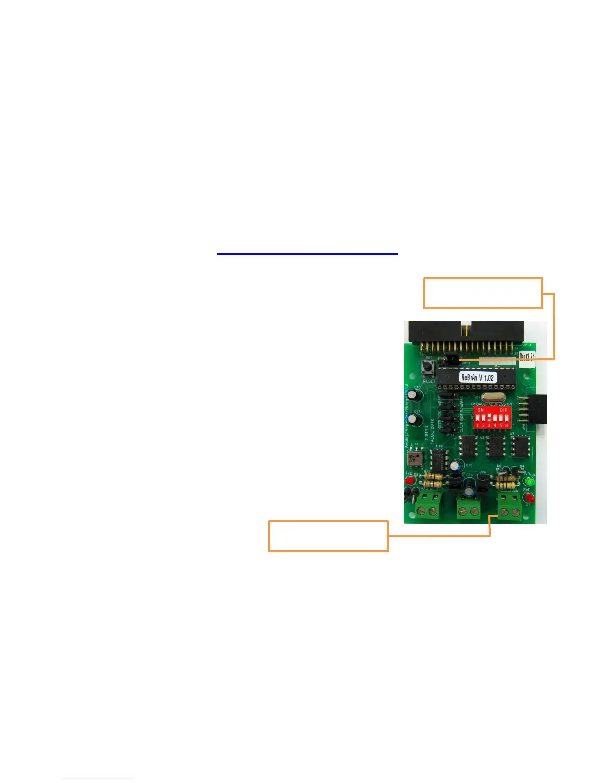
9.2.3 RS485 Bridge
The third function of the REBRAN board is to serve as a BRIDGE
on the RS485 communication line between the DREAM and remote
interfaces. The bridge improves the communication with the
remote interfaces connected to it.
On one side the bridge is plugged into the DREAM’S motherboard
and on the other side it is connected to the remote interfaces by
cable of 2 wires.
The address setting of the BRIDGE must be done in a careful
way. It is important to set the address switch of the BRIDGE to
an address that is higher than the addresses of the interfaces NOT
passing through the BRIDGE and the address of any remote
interfaces working through the bridge must be equal or higher to
the address of the BRIDGE itself.
9.3 The pulses divider
The purpose of the PULSES DIVIDER unit is to enable reading short or high rate pulses by
controllers having a scanning rate of once in a second or lower.
The PULSES DIVIDER expects to receive dry contact Inputs usually arriving from devices such
as water meters or fertilizer meters, it will count the pulses and emit an output pulse per each
JP12 set for BRIDGE
function
The remote terminals
will be connected here