5
The heart of the system is the CPU board, which is in charge of all the decision making of the
controller. The decision making procedure is based on the logic included in the firmware, the
configuration defined by the installer, the programs defined by the user and the current status
of the devices connected to the controller, inputs and outputs.
The input devices consist of sensors that supply information to the CPU and the output devices
are those that are activated by the commands generated by the CPU. However the CPU does
not interact directly with the input/output devices comprising the irrigation network, for that
purpose various kinds of I/O (Inputs/Outputs) Interfaces are used. The I/O Interfaces will
usually use the services of various I/O boards or RTUs that really execute the output
commands and read the input sensors.
The CPU communicates with all the I/O Interfaces second by second, sending them the
desired status of outputs and receiving back the status of the inputs. The schematic drawing
above shows the various kinds of Interfaces recognized by the DREAM 2 system. A control
system will include an arbitrary combination of these Interfaces; some controllers may include
several Interfaces of the same type. The communication channel between the CPU and the
Interfaces uses the RS485 protocol which enables communication up to a distance of several
kilometers on a two wired line; this enables placing interfaces distantly from the CPU when
needed.
Another function of the CPU is the communication with the external world. This is done through
the internet, utilizing the SERVER which is located somewhere in the cloud. The way to set up
the communication channel will be described below.
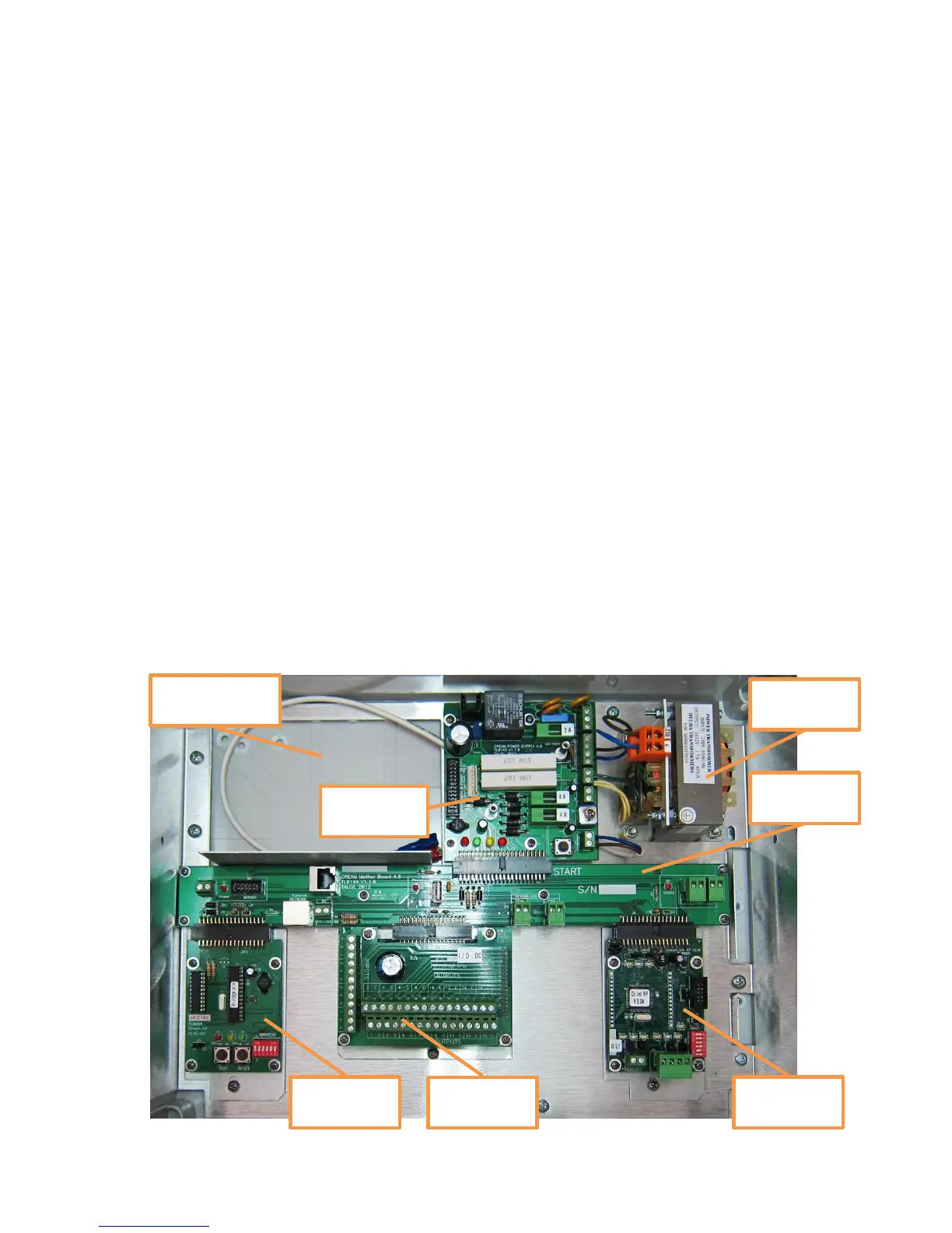
1.1 Looking inside the DREAM 2 case
Location of the
backup battery