28
DREAM
Layer 0
Layer 1
RTU
1
RTU
7
RTU
5
RTU
3
RTU
9
RTU
2
1
2
9
7
5
3
REPEATER
Detailed information about the 2W RTU system can be found in the manual “DREAM 2W
RTU SYSTEM 2007”.
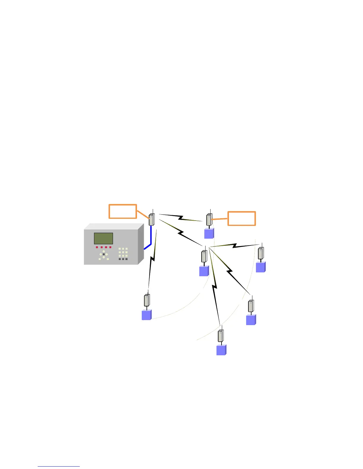
5.3 Interface for radio communicated RTUs
When remote I/O devices cannot be reached by cable, radio communicated RTUs will be used.
The RF INTERFACE will communicate with the RF RTUs through an RF MASTER receiver/
transmitter located on top of a high pole next to the RF INTERFACE. In the field, the RTUs
will be placed next to the I/O devices to be controlled. Each RF RTU consists of an RTU BASE
to which the inputs and outputs are tied, and an RF SLAVE receiver/ transmitter which will also
be installed on top of a high pole. The SLAVES exchange information with the MASTER, each
in its appropriate timeslot, dictated by the RTU’s address. It is expected that there will be a
clear line of sight between the antenna of the RF MASTER and the antennas of the RF
SLAVES otherwise some RF RTUs can be turned into REPEATERs for the benefit of their
neighbors.
Similar to the 2 wired RTUs, the RF RTUs can read digital and analog inputs and activate DC
latching outputs and here again there can be several channels of RF RTUs with up to 60 RTUs
per channel.
Detailed information about the RF RTU system can be found in the manual “DREAM RF RTU
GENERATION III IV and IV.V”.
5.4 Interfaces for local analog inputs
As mentioned above, analog inputs can be read both through the 2W RTU system and the RF
RTU system, however analog sensors located in the close vicinity of the DREAM 2 controller can