58
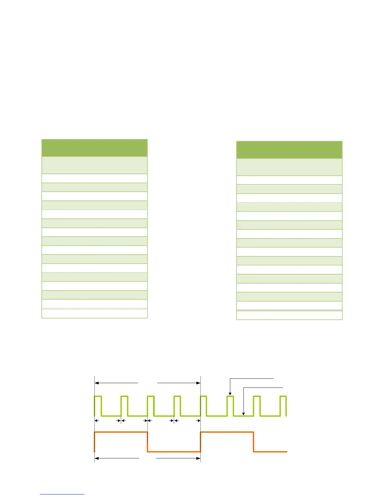
4 pulses
1 pulse
INPUT
OUTPUT
Pulse 1 Pulse 2 Pulse 3 Pulse 4
Positive part
Negative part
"x" input pulses counted. The number “x” is based on the selected setting. A special case is
when “x” equals 1, then for each pulse received at the input there will be one pulse generated
as output. The width of the positive and negative parts of the pulse will be no less than 1
second. This way even if the input pulse was narrow the output pulse will be wide enough not
to be missed by the controller. Obviously, the pulse rate in this case cannot be higher than one
pulse per every 2 seconds.
In the OPERATION TABLES below the Division factor defines how many input pulses will be
represented by each output pulse. Notice that a complete pulse consists of the positive and the
negative parts of the pulse.
EXAMPLE: Let’s assume that Dip switch 5 = OFF (TABLE 1 is selected) and the Dip switches
1-4 are set to: 0100 (division by 4). In this case each 4 pulses at the input will cause 1
symmetric pulse to be emitted at the output. Notice that a complete pulse consists of both the
positive and the negative parts.
OPERATION TABLE 1
(Dip switch 5 = OFF)
OPERATION TABLE 2
(Dip switch 5 = ON)