18
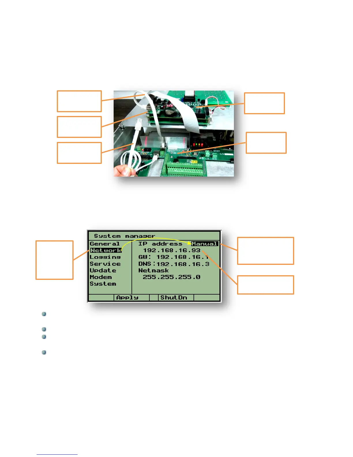
The connection between the DREAM 2 controller and the Router will be by the
External CAT5 cable demonstrated below. There is an Internal Ethernet cable that
goes from the Mother board to the Ethernet Interface card, this cable is supplied
with the system, the other one is not. When both cables are connected properly, the 3
LEDs on the Ethernet interface card D1, D2, D3 are supposed to light with D2 blinking.
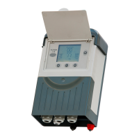
At the System manager/Network screen we are meant to define some addresses as
detailed below. There are two ways for doing that, the Auto mode will automatically detect
the IP, GW and DNS addresses and usually this will be the easiest way to go and there will
be no need for any manual setting. In rare cases Manual setting will be required and then
the person in charge of the local network should supply the following information:
The IP address – This is the address given for the DREAM 2 within the router, or in other
words, this is the address at which the controller can be found on the Internet.
The GW (GateWay address) – is the IP address of the router.
The DNS – it is the address of the DNS (Domain Name System) server to be used for
resolving DNS names into IP addresses.
The Netmask – should be left unchanged.
The parameters will get into effect after rebooting the controller.
At the Router following outgoing ports must be enabled:
ports 55299-55300 (TCP) – for controllers login
port 21 (TCP) – for service update
port 11094 (UDP) – for open vpn
ports 2001-2004 (TCP) – for maintenance and service
Manual or Auto
selection of the
address
The IP address of
the controller
The cursor
is placed
on the
subject -
“Network”