25
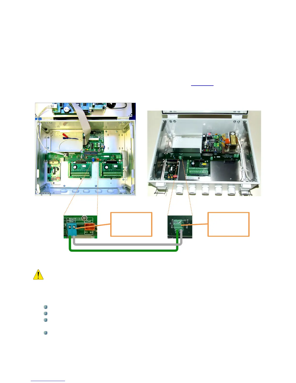
The following pictures show the connection between the DREAM 2 and the I/O expansion
unit. The connection is by a 2 wired cable connected between the remote I/O RS485
terminals on the two motherboards. In case the I/O expansion unit is installed far from the
DREAM there will be a Bridge board added at the DREAM side and the connection will be
through the Bridge which is a special board for connecting remote interfaces (explanation
about the Bridge can be found at the paragraph dealing with the REBRAN board).
Beware of the polarity!! The RS485 communication line has a positive wire marked
“P2” and a negative wire marked “N2”. Do not confuse between them.
A few facts about inputs, outputs and connections to the I/O boards:
Digital Inputs (same on AC and DC I/O boards)
The digital inputs receive dry contact sensors with no polarity.
Each input is connected to the I/O board by 2 wires that may be interchanged.
Several inputs may share one wire as common; it will be connected to any of the
terminals marked by the letter “G”.
Commons of different I/O boards cannot be interconnected.
Remote I/O
RS485 terminal
at the expansion
unit
Remote I/O
RS485 terminal
at the DREAM 2
unit