Tandy 1000
Technical Reference Manual
intel·
8259A18259A-2/8259A-8
THE SPECIAL FULLY NESTED MODE
This
mode
will
be
used
in
the
case
of
a
big
system
where
cascading
is
used, and
the
priority
has
to
be
con·
served
within
each
slave. In
this
case
the
fUlly
nested
mode
will
be
programmed
to
the
master
(using
ICW4).
This
mode
is
similar
to
the
normal
nested
mode
with
the
following
exceptions:
mode,
whenever
the
8259A's
data
bus
outputs
are ena·
bled,
the
SP/EN
output
becomes
active.
This
modification
forces
the
use
of
software
program·
ming
to
determine
whether
the
8259A
is
a
master
or
a
slave.
Bit
3 in ICW4
programs
the
buffered
mode,
and
bit
2 in ICW4
determines
whether
it
is a
master
or
a slave.
CASCADE MODE
a.
When
an
interrupt
request
from
a
certain
slave.is
in
service
this
slave
is
not
locked
out
from
the
master's
priority
logic
and
further
interrupt
requests
from
higher
priority
IR's
within
the
slave
will
be
recognized
by
the
master
and
will
initiate
interrupts
to
the
proc·
essor. (In
the
normal
nested
mode
a slave
is
masked
out
when
its
request
is
in
service
and
no
nigher
requests
from
the
same slave can
be
serviced.)
b.
When
exiting
tM
Interrupt
Service
routine
the
soft·
ware has
to
check
whether
the
interrupt
serviced
was
the
only
one
from
that
slave.
This
is
done
by
sending
a
non·specific
End
of
Interrupt
(EOI)
command
to
the
slave and
then
reading
its
In·Service
register
and
checking
for
zero. If it is
empty,
a
non·specific
EOI
can
be sent
to
the
master
too. If not,
no
EOI
should
be
sent.
BUFFERED MODE
When
the
8259A
is
used in a
large
system
where
bus
driving
buffers
are
required
on
the
data
bus
and
the
cas·
cading
mode
is
used,
there
exists
the
problem
of
enabl·
ing
buffers.
The
buffered
mode
will
structure
the
8259A
to
send an
enable
signal
on
SP/EN
to
enable
the
buffers.
In
this
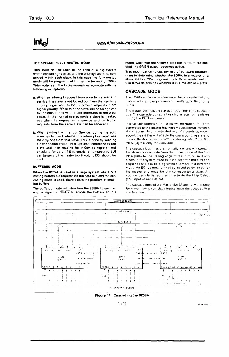
The 8259A can be easily
interconnected
in a system
of
one
master
with
up
to
eight
slaves
to
handle
up
to
64
priority
levels
The master
controls
the slaves
through
the
3 line cascade
bus. The cascade bus acts
like
chip
selects to
the
slaves
during
the
INTA
sequence
In a cascade
configuration,
the
slave
Interrupt
outputs
are
connected
to
the
master
Interrupt
request Inputs. When a
slave request line
IS
activated
and
afterwards
acknowl·
edged, the
master
will enable the
corresponding
slave
to
release
the
deVice
routine
address dUring bytes 2 and 3
of
INTA. (Byte 2
only
for
8086/8088).
The cascade
bus
lines are
normally
low and Will
contain
the slave address code
from
the
trailing
edge
of
the frrst
INTA pulse
to
the
trailing
edge of the thrrd pulse Each
8259A in the system
must
follow
a separate InitializatIOn
sequence
and can be
programmed
to
work
In
a
different
mode.
An
EOI
command
must
be Issued
twice
once
for
the
master
and
once
for
the
corresponding
slave. An
address
decoder
is
requrred
to
activate
the
Chip
Select
(CS)
Input
of
each
8259A
The cascade
lines
of
the
Master 8259A are
activated
only
for
slave
inputs,
non slave
Inputs
leave the cascade
line
Inactive (low)
Cs
"
'N'
/I;
~9A
'"l
AVE.
B
T
G~D
I
1 I
] 6 5 • ]
"l
! !
I I
]~L==-=~_:=,
c-_L-L,-,
-'1
~~~~--r-->-
_~~~~~--=C-=-ON-,--T_RO:..:'.::-.U=S~~~~~~~~~~_
---....----r---...J
II
•
I~r
RtU
~~~'~il
..
__
L~~_
.
------.L-------L--D.-T-.-.,~'s-,.,l--l--
~'.{";
x,
I
,
~
1
-+-
~
l
.J
-~
r - -----<-
---1
, t
~
l.
~~~~~---~-
.~----
-._--.
------T~----
INHRRU"
REQUESTS
Figure
11.
Cascading
the
B259A
2·133
 Loading...


