Tandy 1000
inter
8284A/8284A-1
Technical Reference Manual
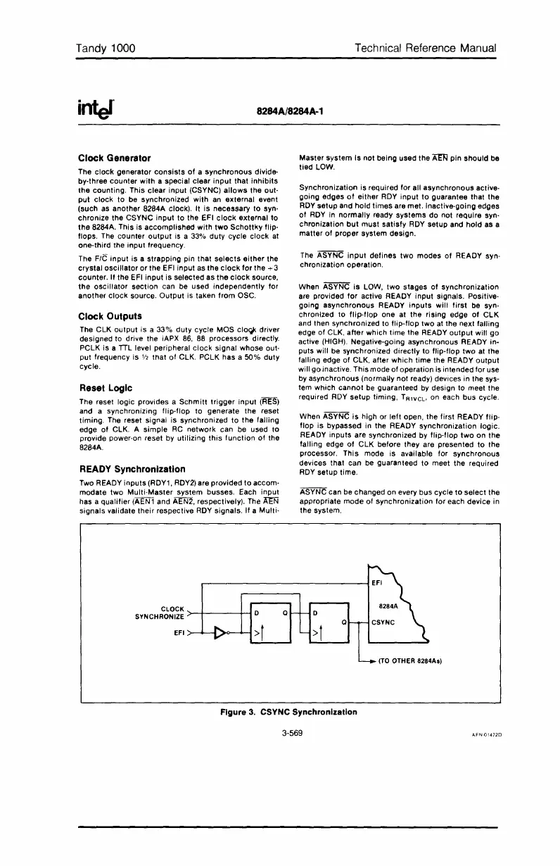
Clock Generator
The
clock
generator
consists
of
a
synchronous
divide-
by-three
counter
with
a special
clear
input
that
inhibits
the
counting.
This
clear
input
(CSYNC)
allows
the
out-
put
clock
to
be synchronized
with
an external event
(such as
another
8284A clock). It
is
necessary
to
syn-
chronize
the
CSYNC
input
to
the EFI clOCk external
to
the
8284A. This is
accomplished
with
two
Schottky
flip-
flops. The
counter
output
is a 33%
duty
cycle
clock
at
one-third
the
input
frequency.
The
FIG
input
is
a
strapping
pin that
selects
either
the
crystal
oscillator
or
the
EFI input as
the
clock
for
the
...
3
counter.
If
the
EFI
input
is
selected
as
the
clock
source,
the
oscillator
section
can be used
independently
for
another
clock
source.
Output
is taken
from
OSC.
Clock Outputs
The
ClK
output
is a
33%
duty
cycle
MaS
clo~
driver
designed
to drive the iAPX
86,
88 processors directly.
PClK
is a
TIL
level peripheral
clock
signal
whose
out-
put frequency
is
V2
tMt
of
ClK.
PClK
has a
50%
duty
cycle.
Reset Logic
The reset logic provides a
Schmitt
trigger
input
(RES)
and a
synchronizing
flip-flop
to
generate the reset
timing.
The reset signal
is
synchronized
to
the
falling
edge
of
ClK.
A
simple
RC
network
can be used
to
provide power-on reset by
utilizing
this
function
of
the
8284A.
READY Synchronization
Two READY
inputs
(RDY1, RDY2) are
provided
to
accom-
modate
two
Multi-Master
system
busses. Each
input
has a
qualifier
(AEN1 and AEN2, respectively). The
A8;j
signals
validate
their
respective RDY signals.
If
a Multi-
Master
system
is
not
being
used
the
Am
pin
should
be
tied
lOW.
Synchronization
is required
for
all
asynchronous
active-
going
edges
of
either
ROY
input
to
guarantee that
the
ROY
setup
and
hold
times
are met. Inactive-going edges
of
ROY
in
normally
ready
systems
do
not
require syn-
chronization
but
must
satisfy
ROY
setup
and
hold
as a
matter
of
proper
system
design.
The ASYNC
input
defines
two
modes
of
READY syn-
chronization
operation.
When ASYNC
is
lOW,
two
stages
of
synchronization
are provided
for
active READY
input
signals. Positive-
going
asynchronous
READY
inputs
will
first
be syn-
chronized
to
flip·f1op one
at
the
rising
edge
of
ClK
and then synchronized to
flip-flop
two
at
the
next
falling
edge
of
ClK,
after
which
time
the READY
output
will
go
active (HIGH). Negative-going asynchronous READY in-
puts will be synchronized
directly
to
flip-flop
two
at the
falling edge
of
ClK,
alter
which
time the READY
output
will
go
inactive.
This
mode
of
operation
is intended
for
use
by
asynchronous
(norma~y
not
ready) devices
in
the sys-
tem Which
cannot
be
guaranteed by design to meet
the
required RDY
setup
timing,
T
R1VCL,
on each bus cycle.
When ASYNC
is
high or
left
open, the
first
READY flip-
flop
is
bypassed
in the READY
synchronization
logic.
READY
inputs
are synChronized by
flip-flop
two
on
the
falling
edge
of
ClK
before they are presented
to
the
processor.
This
mode
is
available
for
synchronous
devices
that
can be guaranteed
to
meet
the
required
RDY
setup
time.
ASYNC can be changed
on
every bus
cycle
to
select
the
appropriate
mode
of
synchronization
for
each
device
in
the
system.
Figure
3.
CSYNC Synchronization
3-569
 Loading...


